Arduino Nano Controlled RF Receiver with LED Indicators and Linear Actuator
Circuit Documentation
Summary
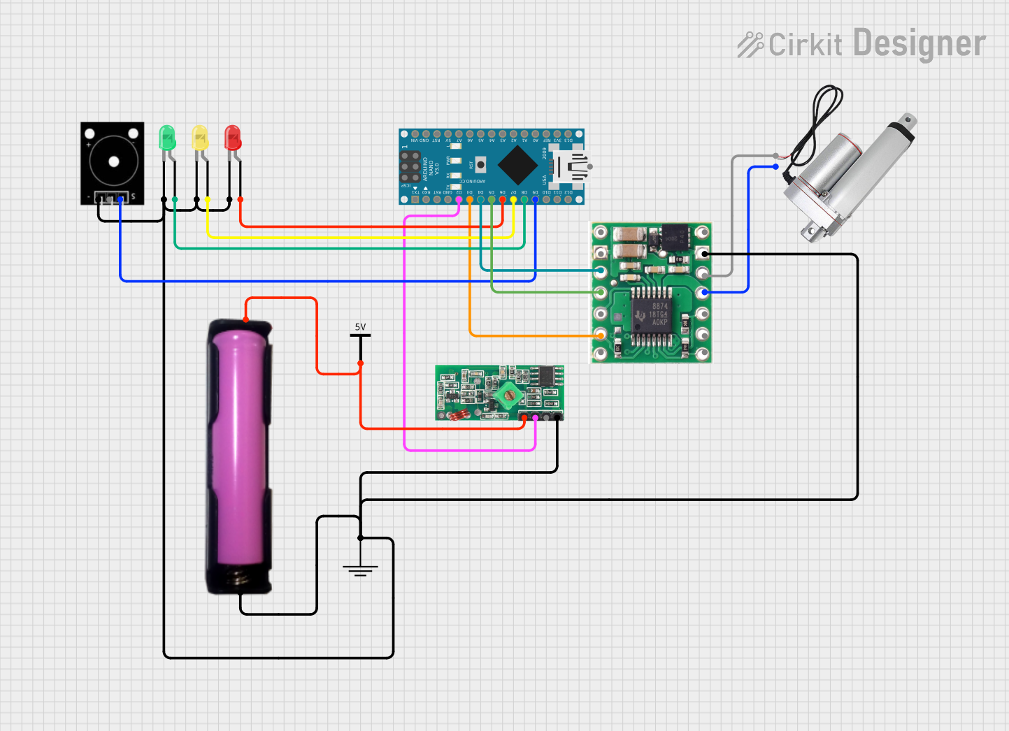
This circuit incorporates a variety of components including an Arduino Nano microcontroller, multiple LEDs of different colors, a 433 MHz RF Receiver Module, an Elegoo Passive Buzzer, a DRV8874 motor driver, a linear actuator, a battery holder with an 18650 battery, and common power rails for ground (GND) and voltage supply (Vcc). The Arduino Nano is used as the central processing unit, interfacing with the RF receiver module, controlling the LEDs and the buzzer, and driving the linear actuator through the motor driver. The circuit is powered by the 18650 battery, with power distribution managed through the Vcc and GND rails.
Component List
- Arduino Nano: A compact microcontroller board based on the ATmega328P, featuring digital and analog I/O pins.
- LED: Two Pin (red): A red light-emitting diode with an anode and cathode for indicating statuses or events.
- LED: Two Pin (green): A green light-emitting diode similar to the red LED, used for status indication.
- LED: Two Pin (yellow): A yellow light-emitting diode, also used for status indication.
- 433 MHz RF Receiver Module: A radio frequency receiver module operating at 433 MHz for wireless communication.
- Elegoo Passive Buzzer: A passive buzzer component that can generate tones when driven by a PWM signal.
- DRV8874: A motor driver IC capable of driving a bidirectional DC motor or actuator.
- Linear actuator: An electromechanical device that creates motion in a straight line, driven by the motor driver.
- 18650 in holder: A rechargeable lithium-ion battery in a holder, providing power to the circuit.
- GND (Ground): A common ground rail for the circuit.
- Vcc (Voltage supply): A common voltage supply rail for the circuit.
Wiring Details
Arduino Nano
- D2 connected to 433 MHz RF Receiver Module DATA
- D3 connected to DRV8874 SLEEP
- D4 connected to DRV8874 IN1/EN
- D5 connected to DRV8874 IN2/PH
- D6 connected to LED (red) anode
- D7 connected to LED (yellow) anode
- D8 connected to LED (green) anode
- D9 connected to Elegoo Passive Buzzer OUTPUT
LED: Two Pin (red)
- Cathode connected to common GND
LED: Two Pin (green)
- Cathode connected to common GND
LED: Two Pin (yellow)
- Cathode connected to common GND
433 MHz RF Receiver Module
- DATA connected to Arduino Nano D2
- VCC connected to common Vcc
- GND connected to common GND
Elegoo Passive Buzzer
- OUTPUT connected to Arduino Nano D9
- GND connected to common GND
DRV8874
- SLEEP connected to Arduino Nano D3
- IN1/EN connected to Arduino Nano D4
- IN2/PH connected to Arduino Nano D5
- GND connected to common GND
- OUT 1 connected to Linear actuator +
- OUT 2 connected to Linear actuator -
Linear actuator
- connected to DRV8874 OUT 1
- connected to DRV8874 OUT 2
18650 in holder
- VCC connected to common Vcc
- GND connected to common GND
GND (Ground)
- All GND connections from various components are tied to this common ground rail.
Vcc (Voltage supply)
- All Vcc connections from various components are tied to this common voltage supply rail.
Documented Code
Arduino Nano Code (sketch.ino)
void setup() {
  // put your setup code here, to run once:

}

void loop() {
  // put your main code here, to run repeatedly:

}
The provided code for the Arduino Nano is a template with empty setup() and loop() functions. The setup() function is intended to contain initialization code that runs once when the microcontroller is powered on or reset. The loop() function is designed to contain the main logic of the program, which will be executed repeatedly as long as the microcontroller is powered.
Additional Notes
The code for the Arduino Nano is currently a placeholder and needs to be populated with the specific logic required to control the components in the circuit based on the desired functionality. This may include reading data from the RF receiver module, controlling the state of the LEDs, generating tones with the buzzer, and driving the linear actuator using the motor driver.