
Circuit Documentation
Summary
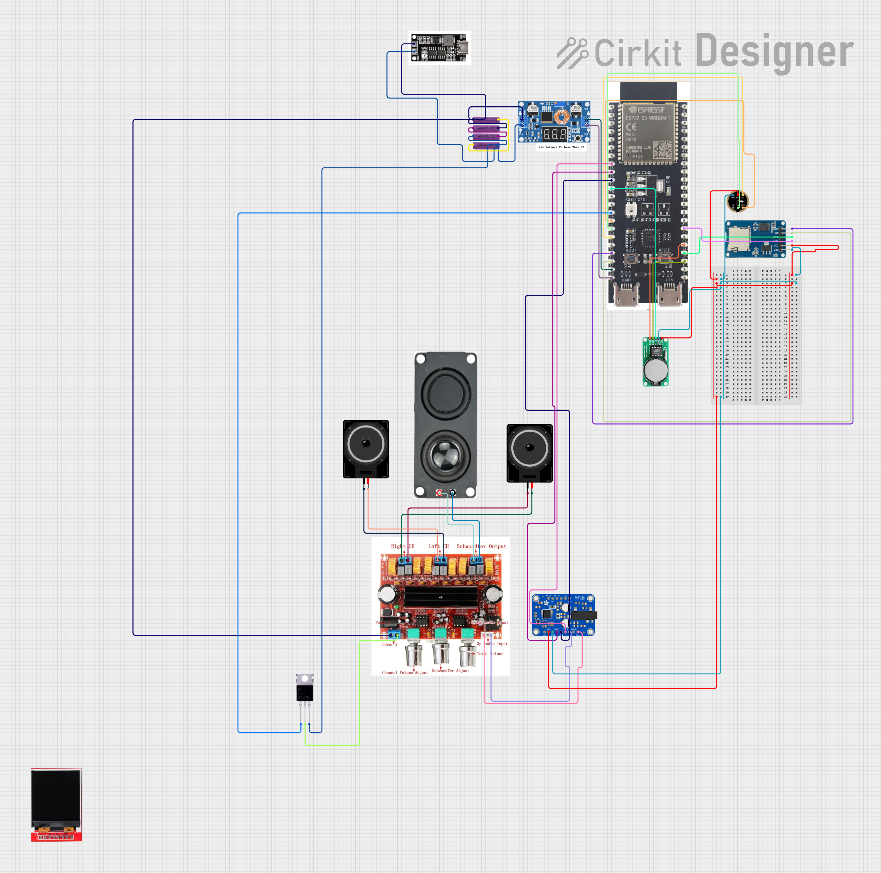
This circuit appears to be a complex audio processing system with power management, a real-time clock, a microcontroller for control logic, data storage, and output to various speakers. The system is powered by a series of 3.7V batteries, regulated by an XL4015 DC Buck Step-down converter. The ESP32 S3 N32R8V microcontroller serves as the central processing unit, interfacing with a real-time clock (DS1302 RTC), a microphone (INMP441), a micro SD card module for data storage, and an I2S DAC (Adafruit UDA1334) for audio signal processing. The audio output is managed by a PAM3116D2 2.1 amplifier that drives a stereo pair of loudspeakers and a subwoofer.
Component List
- 3.7V Battery: Provides power to the circuit.
- XL4015 5A DC Buck Step-down Converter: Steps down voltage for the circuit.
- Loudspeaker: Converts electrical signals into sound.
- 8 OHM 20W Speaker: A high-power speaker for low-frequency (subwoofer) output.
- PAM3116D2 2.1 Amplifier: Amplifies audio signals for the speakers.
- DS1302 RTC: Real-time clock for timekeeping.
- INMP441 Front Mic: Captures audio signals.
- Micro SD Card Module: Provides data storage capability.
- TFT LCD Display ST7735S: A small display for visual output.
- Adafruit UDA1334 I2S DAC: Digital-to-analog converter for audio signals.
- MRB045: Power management module.
- Mosfet: Acts as an electronic switch.
- ESP32 S3 N32R8V: Microcontroller for processing and control.
Wiring Details
Power Management
- 3.7V Batteries: Connected in series and parallel to provide the required voltage and current.
- XL4015 5A DC Buck Step-down Converter: Input connected to the batteries, output provides regulated voltage to the ESP32 and other components.
Audio Path
- INMP441 Front Mic: Captures audio and sends it to the ESP32 for processing.
- Adafruit UDA1334 I2S DAC: Receives digital audio from the ESP32 and converts it to an analog signal.
- PAM3116D2 2.1 Amplifier: Amplifies the analog audio signal from the DAC and drives the loudspeakers and subwoofer.
Control and Storage
- DS1302 RTC: Keeps track of time, interfaced with the ESP32.
- Micro SD Card Module: Stores data, controlled by the ESP32.
- ESP32 S3 N32R8V: Central processing unit, controls the DAC, RTC, microphone, SD card module, and communicates with the display.
Output Devices
- Loudspeakers: Receive amplified audio signals from the PAM3116D2 amplifier.
- 8 OHM 20W Speaker: Serves as the subwoofer, connected to the subwoofer output of the PAM3116D2 amplifier.
- TFT LCD Display ST7735S: Displays information, controlled by the ESP32.
Power Control
- Mosfet: Used to switch power to components under the control of the ESP32.
Documented Code
Microcontroller Code (ESP32 S3 N32R8V)
void setup() {
  // put your setup code here, to run once:

}

void loop() {
  // put your main code here, to run repeatedly:

}
The provided code is a template with empty setup() and loop() functions, which are the standard structure for Arduino sketches. The setup() function is intended for code that runs once upon reset or power-up, such as pin mode declarations and initializations. The loop() function contains code that runs continuously, handling the main tasks of the microcontroller.
Additional Notes
- The code for the ESP32 S3 N32R8V is minimal and does not include any specific functionality. It will need to be developed to handle the interfacing with the various components mentioned above.
- There is a placeholder for a "documentation.txt" file, but no content was provided for it.
This documentation provides an overview of the circuit and its components, along with the initial code structure for the microcontroller. Further development and detailed implementation of the code are required to achieve the intended functionality of the circuit.