Cirkit Designer
Your all-in-one circuit design IDE
Home /
Project Documentation
Remote-Controlled BLDC Motor and Servo System with FLYSKY Receiver
Circuit Documentation
Summary
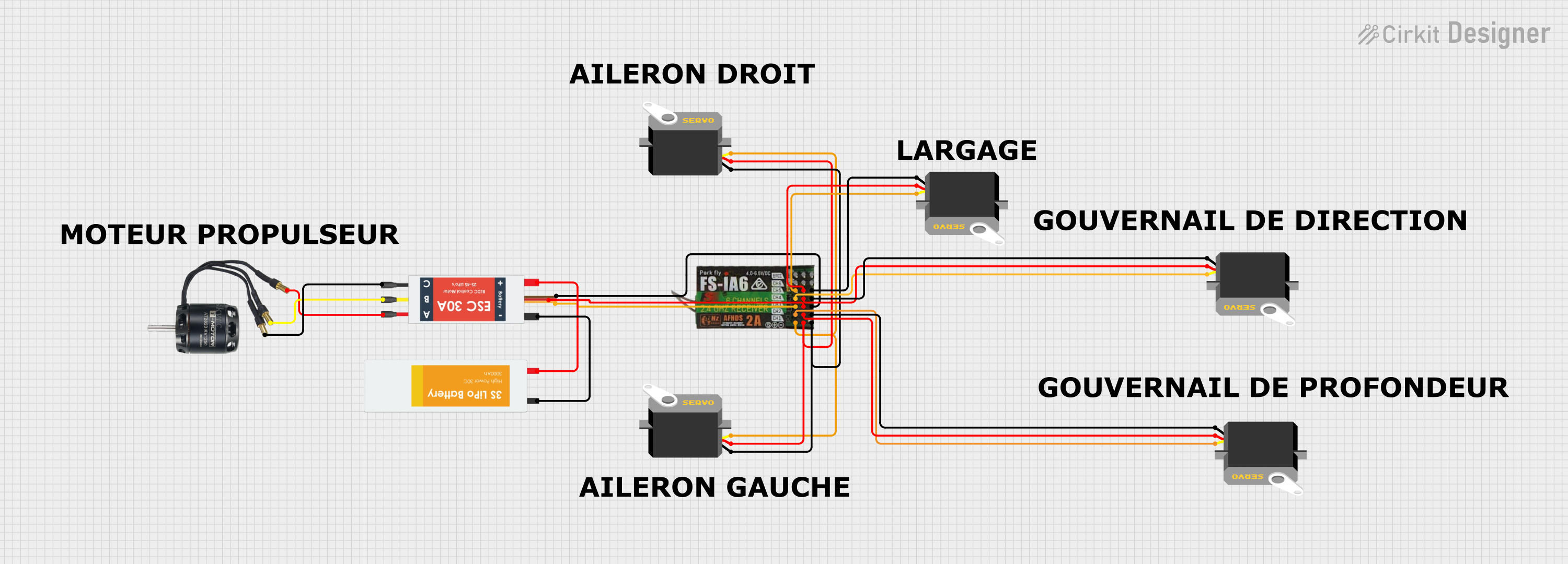
This document provides a detailed overview of a circuit designed to control multiple servos and a BLDC motor using an Electronic Speed Controller (ESC) and a FLYSKY FS-IA6 receiver. The circuit is powered by a LiPo battery and includes several servos for various control functions.
Component List
Electronic Speed Controller (ESC)
- Description: Controls the speed of the BLDC motor.
- Pins: Battery VCC, Battery GND, Signal, 5v out, GND out, M1, M2, M3
Servo
- Description: Actuators for various control functions.
- Pins: gnd, vcc, pulse
BLDC Motor
- Description: Brushless DC motor controlled by the ESC.
- Pins: Wire A, Wire B, Wire C
Lipo Battery
- Description: Provides power to the circuit.
- Pins: VCC, GND
FLYSKY FS-IA6
- Description: Receiver for remote control signals.
- Pins: CH1, 5V, GND, CH2, CH3, CH4, CH5, CH6, VCC
Wiring Details
Electronic Speed Controller (ESC)
- Battery VCC connected to Lipo Battery VCC
- Battery GND connected to Lipo Battery GND
- Signal connected to FLYSKY FS-IA6 CH3
- 5v out connected to FLYSKY FS-IA6 5V
- GND out connected to FLYSKY FS-IA6 GND
- M1 connected to BLDC Motor Wire A
- M2 connected to BLDC Motor Wire B
- M3 connected to BLDC Motor Wire C
Servo 1
- gnd connected to FLYSKY FS-IA6 GND
- vcc connected to FLYSKY FS-IA6 5V
- pulse connected to FLYSKY FS-IA6 CH1
Servo 2
- gnd connected to FLYSKY FS-IA6 GND
- vcc connected to FLYSKY FS-IA6 5V
- pulse connected to FLYSKY FS-IA6 CH1
Servo 3
- gnd connected to FLYSKY FS-IA6 GND
- vcc connected to FLYSKY FS-IA6 5V
- pulse connected to FLYSKY FS-IA6 CH2
Servo 4
- gnd connected to FLYSKY FS-IA6 GND
- vcc connected to FLYSKY FS-IA6 5V
- pulse connected to FLYSKY FS-IA6 CH4
Servo 5
- gnd connected to FLYSKY FS-IA6 GND
- vcc connected to FLYSKY FS-IA6 5V
- pulse connected to FLYSKY FS-IA6 CH5
BLDC Motor
- Wire A connected to Electronic Speed Controller (ESC) M1
- Wire B connected to Electronic Speed Controller (ESC) M2
- Wire C connected to Electronic Speed Controller (ESC) M3
Lipo Battery
- VCC connected to Electronic Speed Controller (ESC) Battery VCC
- GND connected to Electronic Speed Controller (ESC) Battery GND
FLYSKY FS-IA6
- CH1 connected to Servo 1 pulse and Servo 2 pulse
- 5V connected to Servo 1 vcc, Servo 2 vcc, Servo 3 vcc, Servo 4 vcc, Servo 5 vcc, and Electronic Speed Controller (ESC) 5v out
- GND connected to Servo 1 gnd, Servo 2 gnd, Servo 3 gnd, Servo 4 gnd, Servo 5 gnd, and Electronic Speed Controller (ESC) GND out
- CH2 connected to Servo 3 pulse
- CH3 connected to Electronic Speed Controller (ESC) Signal
- CH4 connected to Servo 4 pulse
- CH5 connected to Servo 5 pulse
Code
No microcontroller code is provided for this circuit.
This documentation provides a comprehensive overview of the components and their interconnections within the circuit. For further details or modifications, please refer to the specific component datasheets and user manuals.