
Arduino UNO-Based Smart Irrigation and Lighting System with Wi-Fi Control
View and Edit Project In Cirkit Designer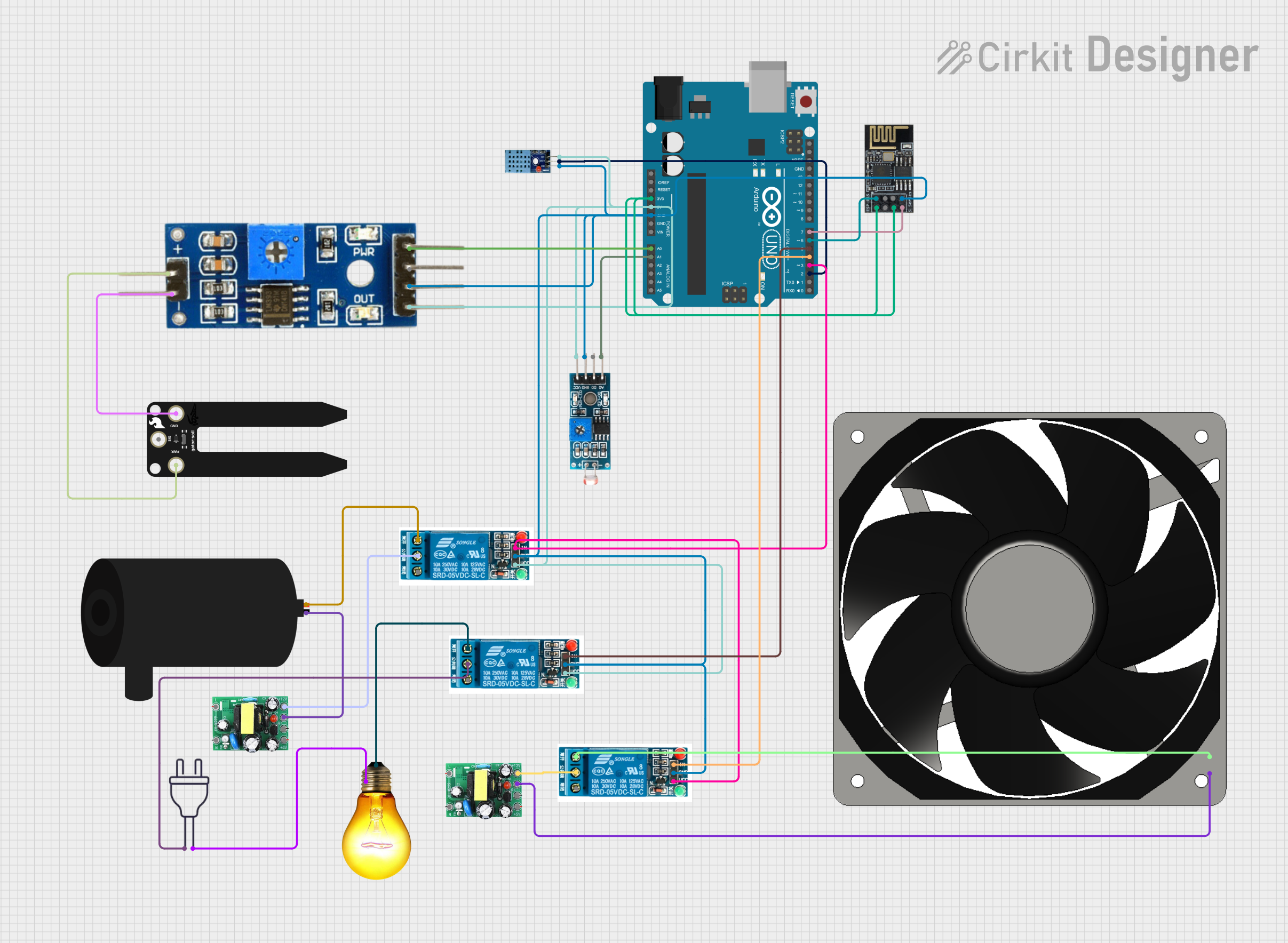
Circuit Documentation
Summary
This document provides a detailed overview of a circuit designed to monitor environmental conditions and control devices such as a water pump, AC bulb, and a fan. The circuit includes sensors for temperature, humidity, soil moisture, and light intensity, and it uses an Arduino UNO microcontroller to process the data and control the devices. The circuit also includes a WiFi module for remote monitoring and control.
Component List
DHT 11
- Pins: VCC, GND, DATA
- Description: Temperature and Humidity Sensor
- Purpose: Measures temperature and humidity levels.
Soil Moisture Module
- Pins: positive, negative, Analog, Digital, Ground, VCC
- Description: Soil Moisture Sensor
- Purpose: Measures the moisture level in the soil.
Module LDR
- Pins: VCC, GND, DO, AO
- Description: Light Dependent Resistor Module
- Purpose: Measures light intensity.
Water Pump
- Pins: positive, negative
- Description: Water Pump
- Purpose: Pumps water for irrigation.
AC Bulb
- Pins: P, N
- Description: AC Bulb
- Purpose: Provides illumination.
5V Relay
- Pins: Normally Open, Common terminal, Normally Closed, In, GND, VCC
- Description: Relay Module
- Purpose: Controls high voltage devices.
WiFi Module ESP8266-01
- Pins: RX, GPIO0, GPIO2, GND, +3V3, Reset, CH-PD Chip power down, TX
- Description: WiFi Module
- Purpose: Provides WiFi connectivity.
SparkFun gator:soil
- Pins: VCC, GND, SIG
- Description: Soil Moisture Sensor
- Purpose: Measures the moisture level in the soil.
Arduino UNO
- Pins: UNUSED, IOREF, Reset, 3.3V, 5V, GND, Vin, A0, A1, A2, A3, A4, A5, SCL, SDA, AREF, D13, D12, D11, D10, D9, D8, D7, D6, D5, D4, D3, D2, D1, D0
- Description: Microcontroller
- Purpose: Central processing unit for the circuit.
actodc
- Pins: 12v, -, 5v, live, neutral
- Description: AC to DC Converter
- Purpose: Converts AC power to DC power.
Power 220V
- Pins: hot wire, neutral wire
- Description: Power Source
- Purpose: Provides 220V AC power.
120 Fan 12V
- Pins: 12V+, GND
- Description: Fan
- Purpose: Provides ventilation.
Wiring Details
DHT 11
- VCC connected to 5V of Arduino UNO
- GND connected to GND of Arduino UNO
- DATA connected to D2 of Arduino UNO
Soil Moisture Module
- VCC connected to 5V of Arduino UNO
- Ground connected to GND of Arduino UNO
- Analog connected to A0 of Arduino UNO
- positive connected to VCC of SparkFun gator:soil
- negative connected to GND of SparkFun gator:soil
Module LDR
- VCC connected to 5V of Arduino UNO
- GND connected to GND of Arduino UNO
- AO connected to A1 of Arduino UNO
Water Pump
- positive connected to Normally Open of 5V Relay
- negative connected to - of actodc
AC Bulb
- P connected to Normally Open of 5V Relay
- N connected to neutral wire of Power 220V
5V Relay (1)
- VCC connected to 5V of Arduino UNO
- GND connected to GND of Arduino UNO
- In connected to D5 of Arduino UNO
- Common terminal connected to 12v of actodc
- Normally Open connected to positive of Water Pump
5V Relay (2)
- VCC connected to 5V of Arduino UNO
- GND connected to GND of Arduino UNO
- In connected to D4 of Arduino UNO
- Common terminal connected to 12v of actodc
- Normally Open connected to 12V+ of 120 Fan 12V
5V Relay (3)
- VCC connected to 5V of Arduino UNO
- GND connected to GND of Arduino UNO
- In connected to D3 of Arduino UNO
- Common terminal connected to 12v of actodc
- Normally Open connected to P of AC Bulb
WiFi Module ESP8266-01
- +3V3 connected to 3.3V of Arduino UNO
- CH-PD Chip power down connected to 3.3V of Arduino UNO
- GND connected to GND of Arduino UNO
- TX connected to D7 of Arduino UNO
- RX connected to D6 of Arduino UNO
SparkFun gator:soil
- VCC connected to positive of Soil Moisture Module
- GND connected to negative of Soil Moisture Module
Arduino UNO
- 3.3V connected to +3V3 and CH-PD Chip power down of WiFi Module ESP8266-01
- 5V connected to VCC of DHT 11, Soil Moisture Module, Module LDR, and all 5V Relays
- GND connected to GND of DHT 11, Soil Moisture Module, Module LDR, WiFi Module ESP8266-01, and all 5V Relays
- A0 connected to Analog of Soil Moisture Module
- A1 connected to AO of Module LDR
- D2 connected to DATA of DHT 11
- D3 connected to In of 5V Relay (3)
- D4 connected to In of 5V Relay (2)
- D5 connected to In of 5V Relay (1)
- D6 connected to RX of WiFi Module ESP8266-01
- D7 connected to TX of WiFi Module ESP8266-01
actodc (1)
- 12v connected to Common terminal of 5V Relay (1)
- - connected to negative of Water Pump
actodc (2)
- 12v connected to Common terminal of 5V Relay (2)
- - connected to GND of 120 Fan 12V
Power 220V
- hot wire connected to Common terminal of 5V Relay (3)
- neutral wire connected to N of AC Bulb
120 Fan 12V
- 12V+ connected to Normally Open of 5V Relay (2)
- GND connected to - of actodc (2)
Documented Code
Arduino UNO Code (sketch.ino)
void setup() {
  // put your setup code here, to run once:

}

void loop() {
  // put your main code here, to run repeatedly:

}
Additional Documentation (documentation.txt)