
Arduino-Controlled RGB LED Lighting with Bluetooth Interface
View and Edit Project In Cirkit Designer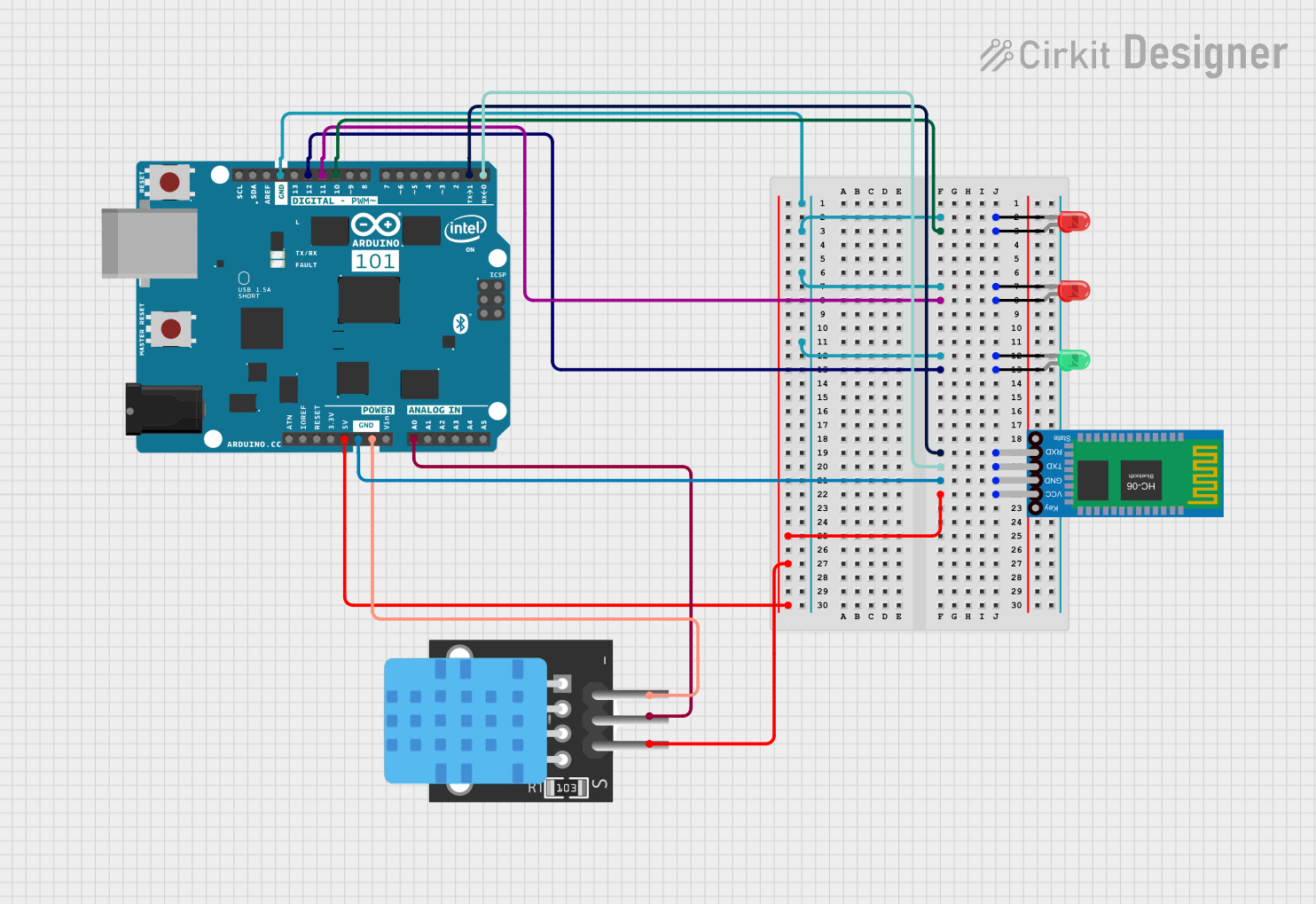
Circuit Documentation
Summary of the Circuit
This circuit is designed to interface an Arduino 101 microcontroller with a set of LEDs and a Bluetooth HC-06 module, as well as a temperature sensor (TEMP). The LEDs are controlled by the Arduino through PWM-capable pins, allowing for brightness control or other PWM-based modulation. The Bluetooth module enables wireless communication, potentially for remote control or data transmission to/from the Arduino. The temperature sensor is connected to an analog input for temperature monitoring.
Component List
LEDs
LED: Two Pin (red)
- Description: A standard red LED with two pins: anode and cathode.
- Purpose: To provide visual indication or feedback.
LED: Two Pin (green)
- Description: A standard green LED with two pins: anode and cathode.
- Purpose: To provide visual indication or feedback.
Microcontroller
- Arduino 101
- Description: A microcontroller board based on the Intel Curie module, with a variety of digital and analog I/O pins.
- Purpose: To control the LEDs, read sensor data, and manage Bluetooth communication.
Temperature Sensor
- TEMP
- Description: A temperature sensor with a digital output.
- Purpose: To monitor temperature and provide feedback to the Arduino.
Bluetooth Module
- Bluetooth HC-06
- Description: A Bluetooth module for wireless communication.
- Purpose: To enable wireless data exchange with the Arduino.
Wiring Details
LED: Two Pin (red)
- Cathode: Connected to the Arduino's GND.
- Anode: Connected to the Arduino's digital pins (D10 PWM/SS or D11 PWM/MOSI) for PWM control.
LED: Two Pin (green)
- Cathode: Connected to the Arduino's GND.
- Anode: Connected to the Arduino's digital pin (D12/MISO) for PWM control.
Arduino 101
- GND: Common ground for LEDs, Bluetooth HC-06, and TEMP sensor.
- D10 PWM/SS: Connected to the anode of one red LED for PWM control.
- D11 PWM/MOSI: Connected to the anode of the other red LED for PWM control.
- D12/MISO: Connected to the anode of the green LED for PWM control.
- D1/TX: Connected to the RXD pin of the Bluetooth HC-06 for serial communication.
- D0/RX: Connected to the TXD pin of the Bluetooth HC-06 for serial communication.
- 5V: Powers the Bluetooth HC-06 and TEMP sensor.
- A0: Connected to the D3 pin of the TEMP sensor for temperature readings.
TEMP Sensor
- 5V: Powered by the Arduino's 5V output.
- D3: Output connected to the Arduino's analog pin A0 for temperature readings.
- GND: Connected to the Arduino's GND.
Bluetooth HC-06
- VCC: Powered by the Arduino's 5V output.
- GND: Connected to the Arduino's GND.
- TXD: Connected to the Arduino's D0/RX for serial communication.
- RXD: Connected to the Arduino's D1/TX for serial communication.
Documented Code
Since no code was provided in the input, this section is currently empty. When code is available, it should be documented here with explanations of its functionality, including setup, main loop, and any functions or libraries used. The code should be formatted properly for readability and include comments explaining the purpose of each section and significant lines of code.