Cirkit Designer
Your all-in-one circuit design IDE
Home /
Project Documentation
Battery-Powered DC Motor Speed Controller Using Potentiometer and TIP120 Transistor
Circuit Documentation
Summary
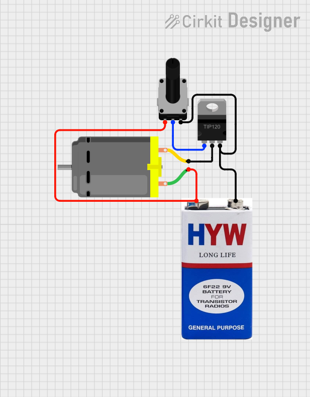
This document provides a detailed overview of a circuit designed to control a DC motor using a rotary potentiometer and a TIP120 Darlington transistor. The circuit is powered by a 9V battery. The rotary potentiometer adjusts the base current of the transistor, which in turn controls the current flowing through the DC motor, thereby adjusting its speed.
Component List
Rotary Potentiometer
- Description: A variable resistor used to adjust the base current of the transistor.
- Pins: leg1, wiper, leg2
- Properties:
- Resistance: 10,000 Ohms
TIP120 Hi-Current Darlington Transistor
- Description: A high-current transistor used to control the DC motor.
- Pins: BASE, COLLECTOR, EMITTER
DC Motor
- Description: A motor that is controlled by the transistor.
- Pins: pin 1, pin 2
9V Battery
- Description: Provides power to the circuit.
- Pins: +, -
Wiring Details
Rotary Potentiometer
- leg1 is connected to the positive terminal (+) of the 9V battery and pin 1 of the DC motor.
- wiper is connected to the BASE of the TIP120 transistor.
- leg2 is connected to the negative terminal (-) of the 9V battery and the EMITTER of the TIP120 transistor.
TIP120 Hi-Current Darlington Transistor
- BASE is connected to the wiper of the rotary potentiometer.
- COLLECTOR is connected to pin 2 of the DC motor.
- EMITTER is connected to the negative terminal (-) of the 9V battery and leg2 of the rotary potentiometer.
DC Motor
- pin 1 is connected to the positive terminal (+) of the 9V battery and leg1 of the rotary potentiometer.
- pin 2 is connected to the COLLECTOR of the TIP120 transistor.
9V Battery
- + is connected to leg1 of the rotary potentiometer and pin 1 of the DC motor.
- - is connected to the EMITTER of the TIP120 transistor and leg2 of the rotary potentiometer.
Code
There is no microcontroller code associated with this circuit.