ESP32 CAM-Based Wi-Fi Motion-Activated Smart Light
Circuit Documentation
Summary
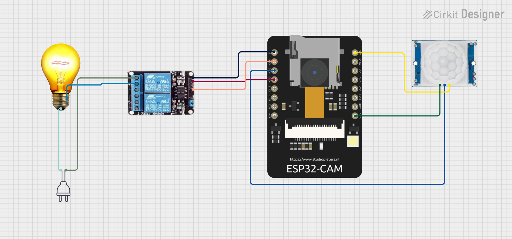
The circuit in question appears to be a motion-activated lighting system. It uses an ESP32 CAM microcontroller to interface with an HC-SR501 PIR motion sensor and control a 2-channel relay, which in turn switches an AC bulb on and off. The ESP32 CAM is powered by a 5V supply, and it also provides a 3.3V power supply to the PIR motion sensor. The relay module is used to safely control the high-voltage AC bulb with the low-voltage signals from the ESP32 CAM. The circuit is designed to activate the lighting when motion is detected by the sensor.
Component List
ESP32 CAM
- Description: A microcontroller module with Wi-Fi and camera capabilities.
- Pins: 5V, GND, GPIO12, GPIO13, GPIO15, GPIO14, GPIO2, GPIO4, 3.3V, GPIO16, GPIO0, 3.3V / 5V / P_OUT, GPIO3 / RX, GPIO1 / TX
HC-SR501 PIR Motion Sensor
- Description: A passive infrared sensor that detects motion by measuring changes in the infrared levels emitted by surrounding objects.
- Pins: Output, Ground, Power Supply
2-Channel Relay
- Description: An electromechanical switch that allows a low-power circuit to switch a relatively high current and/or voltage on and off.
- Pins: NC, COM, NO, VCC, IN2, IN1, GND
AC Bulb
- Description: A standard light bulb designed to operate on AC voltage.
- Pins: P (Phase), N (Neutral)
Power 220V
- Description: A power source providing 220V AC, which is typical in many regions for household power.
- Pins: Hot wire, Neutral wire
Wiring Details
ESP32 CAM
- 5V connected to Relay VCC
- GND connected to Relay GND and PIR Motion Sensor Ground
- GPIO12 connected to PIR Motion Sensor Output
- GPIO13 connected to Relay IN2
- 3.3V connected to PIR Motion Sensor Power Supply
HC-SR501 PIR Motion Sensor
- Output connected to ESP32 CAM GPIO12
- Ground connected to ESP32 CAM GND
- Power Supply connected to ESP32 CAM 3.3V
2-Channel Relay
- VCC connected to ESP32 CAM 5V
- GND connected to ESP32 CAM GND
- IN2 connected to ESP32 CAM GPIO13
- COM connected to AC Bulb N
- NO connected to Power 220V Hot wire
AC Bulb
- P (Phase) connected to Power 220V Neutral wire
- N (Neutral) connected to Relay COM
Power 220V
- Hot wire connected to Relay NO
- Neutral wire connected to AC Bulb P
Documented Code
No code was provided for the microcontroller. The functionality of the circuit as described in the summary is dependent on the implementation of the embedded code, which would typically handle input from the PIR motion sensor and control the relay to switch the AC bulb on and off. Without the code, the circuit's operation cannot be fully documented.