Arduino UNO with NRF24L01 Wireless Data Transmission
Circuit Documentation
Summary
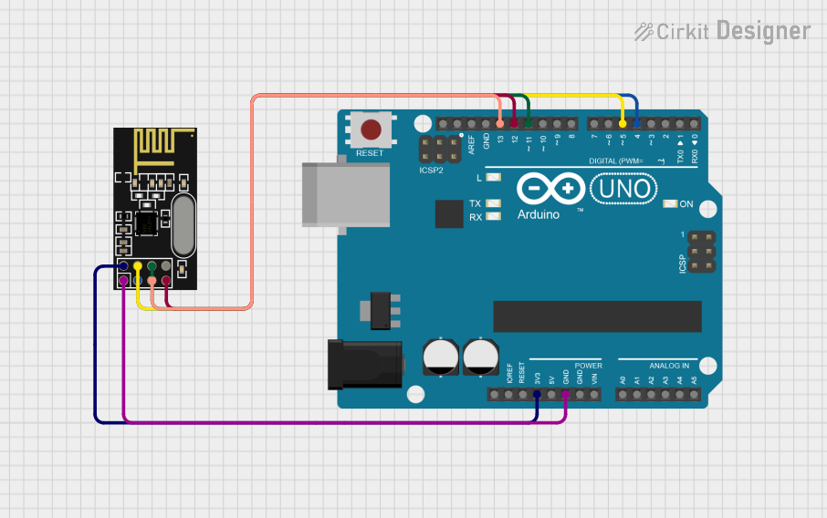
This circuit integrates an Arduino UNO microcontroller board with an NRF24L01 radio frequency transceiver module. The purpose of the circuit is to enable wireless communication capabilities for the Arduino UNO using the NRF24L01 module. The Arduino UNO is programmed to read analog input from a potentiometer (connected to pin A3) and transmit the processed data wirelessly via the NRF24L01 module.
Component List
Arduino UNO
- Description: A microcontroller board based on the ATmega328P.
- Pins Used: IOREF, 3.3V, 5V, GND, Vin, A0-A5, SCL, SDA, AREF, D0-D13.
- Purpose: Acts as the central processing unit of the circuit, reads sensor data, and controls the NRF24L01 module.
NRF24L01
- Description: A 2.4GHz wireless transceiver module.
- Pins Used: IRQ (not used), MOSI, CSN, VCC (3V), GND, CE, SCK, MISO.
- Purpose: Provides wireless communication capabilities to the Arduino UNO.
Wiring Details
Arduino UNO
- 3.3V connected to NRF24L01 VCC (3V)
- GND connected to NRF24L01 GND
- D13 (SCK) connected to NRF24L01 SCK
- D12 (MISO) connected to NRF24L01 MISO
- D11 (MOSI) connected to NRF24L01 MOSI
- D5 (CSN) connected to NRF24L01 CSN
- D4 (CE) connected to NRF24L01 CE
NRF24L01
- VCC (3V) connected to Arduino UNO 3.3V
- GND connected to Arduino UNO GND
- SCK connected to Arduino UNO D13 (SCK)
- MISO connected to Arduino UNO D12 (MISO)
- MOSI connected to Arduino UNO D11 (MOSI)
- CSN connected to Arduino UNO D5 (CSN)
- CE connected to Arduino UNO D4 (CE)
Documented Code
#include <SPI.h>                  // to handle the communication interface with the modem
#include <nRF24L01.h>             // to handle this particular modem driver
#include <RF24.h>                 // the library which helps us to control the radio modem

#define pot_pin A3                // Variable pin of POT is to be connected to analog pin A3
RF24 radio(4,5);                  // Creating instance 'radio'  (CE, CSN) CE -> D4 | CSN -> D5
const byte Address[6] = "00009";  // Address to which data to be transmitted

void setup() {
  Serial.begin(9600);
  pinMode(pot_pin, INPUT);        // Setting A3 (POT pin) as input
  radio.begin();                  // Activate the modem
  radio.openWritingPipe(Address); // Sets the address of transmitter to which program will send the data
}

void loop() {
  radio.stopListening();          // Setting modem in transmission mode
  int value = analogRead(pot_pin); // Reading analog value at pin A3 and storing in variable 'value'
  int data = map(value, 0, 1023, 0, 255); // Converting the 10-bit value to 8-bit
  radio.write(&data, sizeof(data));       // Sending data over NRF 24L01
  Serial.print("Transmitting Data: ");
  Serial.println(data);                   // Printing POT value on serial monitor
}
The code provided is for the Arduino UNO microcontroller. It initializes the serial communication, configures the analog input pin for the potentiometer, and sets up the NRF24L01 module for data transmission. The loop function reads the analog value, maps it to an 8-bit value, and transmits it wirelessly. The transmitted data is also printed to the serial monitor for debugging purposes.