Arduino UNO Based Environmental Monitoring System with Gas, Flame, and Humidity Sensors
Circuit Documentation
Summary
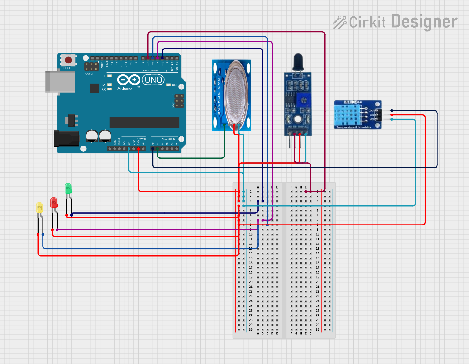
This circuit is designed to monitor environmental parameters such as gas presence, temperature, humidity, and the presence of a flame. It utilizes an Arduino UNO as the central microcontroller to process inputs from an MQ-5 gas sensor, a flame sensor, and a DHT11 temperature and humidity sensor. The circuit also includes three LEDs (red, green, and yellow) that act as indicators for the sensor readings. The Arduino UNO is programmed to read the sensor data and turn on the corresponding LED based on predefined threshold values.
Component List
Arduino UNO
- Microcontroller board based on the ATmega328P
- It has 14 digital input/output pins, 6 analog inputs, a 16 MHz quartz crystal, a USB connection, a power jack, an ICSP header, and a reset button.
MQ-5 Gas Sensor
- A gas sensor designed for detecting LPG, natural gas, and coal gas.
- It has a digital and an analog output.
Flame Sensor
- A sensor for detecting fire and other wavelengths of light.
- It has both digital and analog outputs.
DHT11
- A basic, ultra low-cost digital temperature and humidity sensor.
- It uses a capacitive humidity sensor and a thermistor to measure the surrounding air.
LED: Two Pin (red)
- A basic red LED for indication purposes.
LED: Two Pin (green)
- A basic green LED for indication purposes.
LED: Two Pin (yellow)
- A basic yellow LED for indication purposes.
Wiring Details
Arduino UNO
- GND connected to the ground pins of all other components.
- 5V connected to the VCC pins of MQ-5, Flame Sensor, and DHT11.
- D3 connected to the anode of the green LED.
- D4 connected to the anode of the red LED.
- D5 connected to the anode of the yellow LED.
- D6 connected to the D0 pin of the Flame Sensor.
- A0 connected to the DATA pin of the DHT11.
- A1 connected to the Analog out pin of the MQ-5.
MQ-5 Gas Sensor
- VCC connected to 5V on Arduino UNO.
- GND connected to GND on Arduino UNO.
- Analog out connected to A1 on Arduino UNO.
Flame Sensor
- VCC connected to 5V on Arduino UNO.
- GND connected to GND on Arduino UNO.
- D0 connected to D6 on Arduino UNO.
DHT11
- VCC connected to 5V on Arduino UNO.
- GND connected to GND on Arduino UNO.
- DATA connected to A0 on Arduino UNO.
LED: Two Pin (red)
- Cathode connected to GND on Arduino UNO.
- Anode connected to D4 on Arduino UNO.
LED: Two Pin (green)
- Cathode connected to GND on Arduino UNO.
- Anode connected to D3 on Arduino UNO.
LED: Two Pin (yellow)
- Cathode connected to GND on Arduino UNO.
- Anode connected to D5 on Arduino UNO.
Documented Code
#define led1 3
#define led2 4
#define led3 5
#define gas A1
#define fire 6
#define dh A0

void setup() {
  pinMode(led1, OUTPUT);
  pinMode(led2, OUTPUT);
  pinMode(led3, OUTPUT);
  pinMode(gas, INPUT);
  pinMode(fire, INPUT);
  pinMode(dh, INPUT);

  Serial.begin(9600);
}

void loop() {
  int gas_s = analogRead(gas);
  int dh_s = analogRead(dh);
  int fir = digitalRead(fire);

  Serial.print("gas= ");
  Serial.print(gas_s);

  Serial.print(" dh= ");
  Serial.println(dh_s);

  if (gas_s >= 250) {
    digitalWrite(led1, HIGH);
  } else {
    digitalWrite(led1, LOW);
  }

  if (dh_s >= 500) {
    digitalWrite(led2, HIGH);
  } else {
    digitalWrite(led2, LOW);
  }

  if (fir == 1) {
    digitalWrite(led3, HIGH);
  } else {
    digitalWrite(led3, LOW);
  }
}
This code is designed to read sensor data from the MQ-5 gas sensor, DHT11 sensor, and flame sensor. It then outputs the sensor readings to the serial monitor and controls the state of three LEDs based on the sensor values. The LEDs act as visual indicators for the presence of gas, high temperature/humidity, and flame.