
Arduino-Based Temperature and Humidity Monitor with LCD Display and Adjustable Contrast
View and Edit Project In Cirkit Designer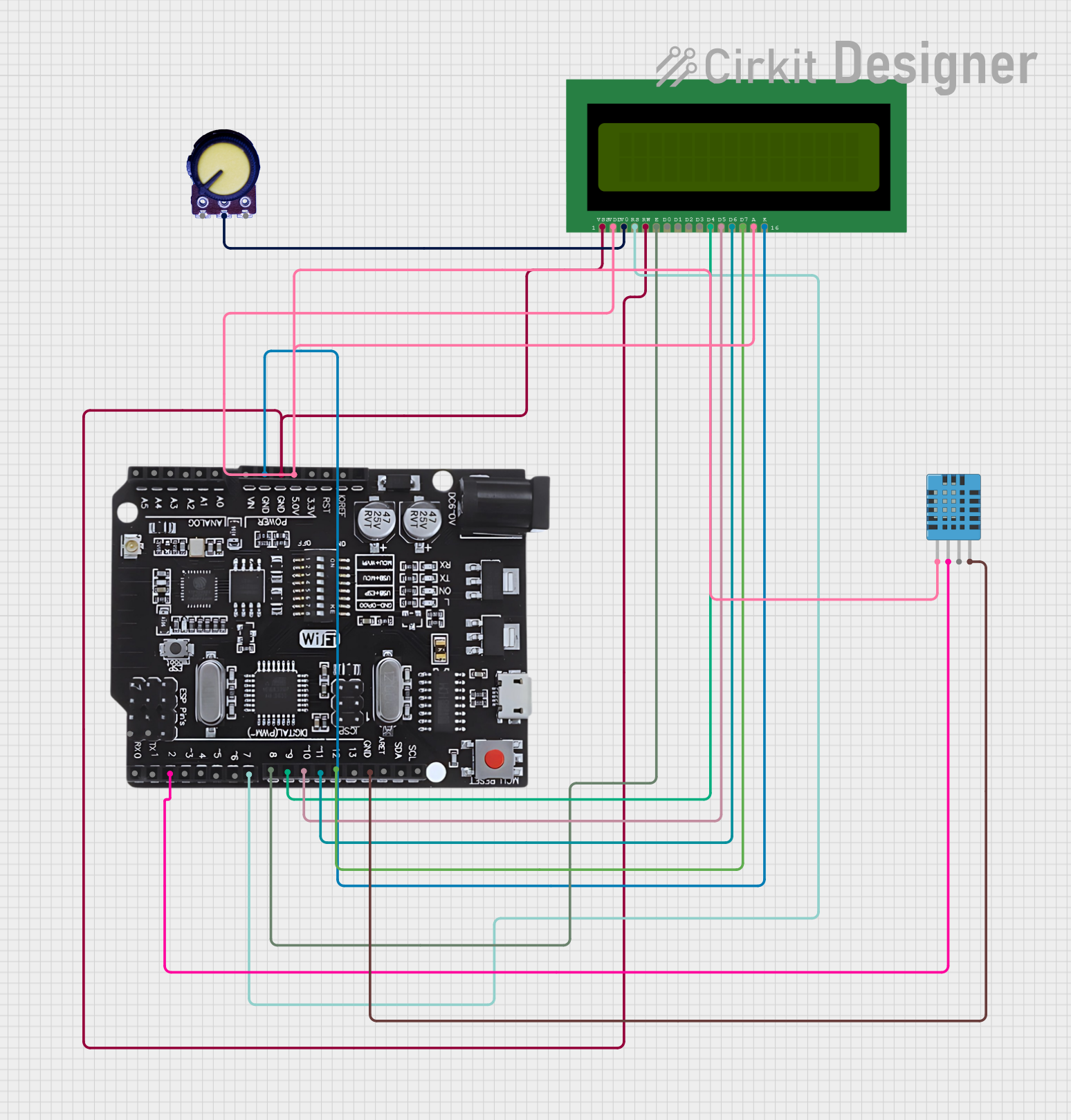
Circuit Documentation
Summary
This circuit reads temperature and humidity data from a DHT11 sensor and displays the values on a 16x2 LCD. A potentiometer is used to adjust the contrast of the LCD display. The circuit is controlled by an Arduino UNO+WiFi R3 ATmega328P+Node MCU ESP8266 CH340G microcontroller.
Component List
DHT11 Humidity and Temperature Sensor
- Description: Measures temperature and humidity.
- Pins: VDD, DATA, NULL, GND
LCD 16x2 (Wokwi Compatible)
- Description: Displays data on a 16x2 character screen.
- Pins: VSS, VDD, V0, RS, RW, E, D0, D1, D2, D3, D4, D5, D6, D7, A, K
Potentiometer
- Description: Adjusts the contrast of the LCD display.
- Pins: GND, Output, VCC
Arduino UNO+WiFi R3 ATmega328P+Node MCU ESP8266 CH340G
- Description: Microcontroller that controls the circuit.
- Pins: KORF, RST, 3.5v, 5.0v, GND, VIN, A0, A1, A2, A3, A4, A5, SCL, SDA, ARET, 13, 12, 11, 10, 9, 8, 7, 6, 5, 4, 3, 2, 1, 0, TX, RX
Wiring Details
DHT11 Humidity and Temperature Sensor
- VDD connected to 5.0v of Arduino
- DATA connected to Pin 2 of Arduino
- GND connected to GND of Arduino
LCD 16x2 (Wokwi Compatible)
- VDD connected to 5.0v of Arduino
- VSS connected to GND of Arduino
- V0 connected to Output of Potentiometer
- RS connected to Pin 7 of Arduino
- RW connected to GND of Arduino
- E connected to Pin 8 of Arduino
- D4 connected to Pin 9 of Arduino
- D5 connected to Pin 10 of Arduino
- D6 connected to Pin 11 of Arduino
- D7 connected to Pin 12 of Arduino
- A connected to 5.0v of Arduino
- K connected to GND of Arduino
Potentiometer
- GND connected to GND of Arduino
- Output connected to V0 of LCD
- VCC connected to 5.0v of Arduino
Arduino UNO+WiFi R3 ATmega328P+Node MCU ESP8266 CH340G
- 5.0v connected to VDD of DHT11 and LCD, A of LCD, VCC of Potentiometer
- GND connected to GND of DHT11, LCD, and Potentiometer
- Pin 2 connected to DATA of DHT11
- Pin 7 connected to RS of LCD
- Pin 8 connected to E of LCD
- Pin 9 connected to D4 of LCD
- Pin 10 connected to D5 of LCD
- Pin 11 connected to D6 of LCD
- Pin 12 connected to D7 of LCD
Code Documentation
/*
 * This Arduino Sketch reads temperature and humidity data from a DHT11 sensor
 * and displays the values on a 16x2 LCD. A potentiometer is used to adjust the
 * contrast of the LCD display.
 */

#include <DHT.h>
#include <LiquidCrystal.h>

#define DHTPIN 2     // Pin connected to DHT11 data pin
#define DHTTYPE DHT11
#define RS 7
#define E 8
#define D4 9
#define D5 10
#define D6 11
#define D7 12

DHT dht(DHTPIN, DHTTYPE);
LiquidCrystal lcd(RS, E, D4, D5, D6, D7);

void setup() {
  // Initialize the LCD
  lcd.begin(16, 2);
  lcd.print("Initializing...");

  // Initialize the DHT sensor
  dht.begin();

  // Print a message to the LCD
  lcd.setCursor(0, 1);
  lcd.print("DHT11 Sensor");
  delay(2000);
  lcd.clear();
}

void loop() {
  // Read temperature and humidity
  float h = dht.readHumidity();
  float t = dht.readTemperature();

  // Check if any reads failed and exit early (to try again).
  if (isnan(h) || isnan(t)) {
    lcd.setCursor(0, 0);
    lcd.print("Sensor error");
    return;
  }

  // Print temperature and humidity to LCD
  lcd.setCursor(0, 0);
  lcd.print("Temp: ");
  lcd.print(t);
  lcd.print(" C");

  lcd.setCursor(0, 1);
  lcd.print("Humidity: ");
  lcd.print(h);
  lcd.print(" %");

  delay(2000); // Wait a few seconds between measurements
}
This code initializes the DHT11 sensor and the LCD display. It reads the temperature and humidity data from the DHT11 sensor and displays the values on the LCD. The potentiometer is used to adjust the contrast of the LCD display.