Cirkit Designer
Your all-in-one circuit design IDE
Home /
Project Documentation
DIP Switch-Controlled Logic Gate LED Indicator Circuit
Circuit Documentation
Summary
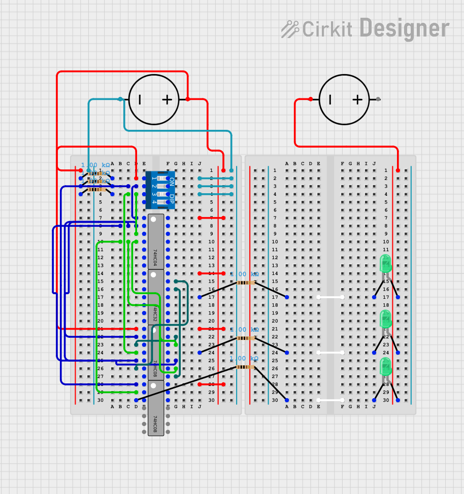
The circuit in question appears to be a digital logic circuit that utilizes a combination of logic gates, resistors, LEDs, a DIP switch, and DC power sources. The circuit's functionality is determined by the state of the DIP switch and the arrangement of the logic gates, which process the switch inputs to drive the LEDs. The resistors are likely used to limit current to the LEDs. Without specific code for microcontrollers, the circuit's behavior is purely combinational logic based on the provided components and their interconnections.
Component List
DC Power Source
- Description: Provides the necessary voltage and ground reference for the circuit.
- Pins: Ground, Positive
Resistor
- Description: Limits current to prevent damage to components such as LEDs.
- Properties: 1000 Ohms resistance
DIP Switch 4 Position
- Description: A manual digital input device with 4 switches that can be independently toggled between on and off positions.
- Pins: 1, 2, 3, 4, 5, 6, 7, 8
74HC08 (AND Gate IC)
- Description: A quad 2-input AND gate integrated circuit.
- Pins: A1, B1, Y1, A2, B2, Y2, GND, VCC, B4, A4, Y4, B3, A3, Y3
74HC04 (NOT Gate IC)
- Description: A hex inverter integrated circuit, each inverter has an input and an output pin.
- Pins: A1, Y1, A2, Y2, A3, Y3, GND, VCC, A6, Y6, A5, Y5, A4, Y4
74HC32 (OR Gate IC)
- Description: A quad 2-input OR gate integrated circuit.
- Pins: A1, B1, Y1, A2, B2, Y2, GND, VCC, B4, A4, Y4, B3, A3, Y3
LED: Two Pin (green)
- Description: A light-emitting diode that emits green light when forward-biased.
- Pins: cathode, anode
Wiring Details
DC Power Source
- Positive connected to:
- VCC of all ICs
- One side of all resistors (except those directly connected to the ground of another DC Power Source)
- Ground connected to:
- GND of all ICs
- Anodes of all LEDs (through another DC Power Source)
Resistor
- pin1 connected to VCC (through DC Power Source)
- pin2 connected to:
- Cathodes of LEDs
- Various pins on DIP Switch and logic ICs
DIP Switch 4 Position
- 1, 2, 3 connected to inputs of 74HC08 (AND Gate IC)
- 6, 7, 8 connected to Ground (through DC Power Source)
74HC08 (AND Gate IC)
- A1, A2, B1, B2, A3, A4, B3, B4 connected to outputs of other logic ICs or DIP Switch
- Y1, Y2, Y3, Y4 connected to inputs of other logic ICs or resistors leading to LEDs
74HC04 (NOT Gate IC)
- A1, A2, A3, A4, A5, A6 connected to outputs of other logic ICs or DIP Switch
- Y1, Y2, Y3, Y4, Y5, Y6 connected to inputs of other logic ICs
74HC32 (OR Gate IC)
- A1, A2, A3, A4, B1, B2, B3, B4 connected to outputs of other logic ICs
- Y1, Y2, Y3, Y4 connected to inputs of other logic ICs or resistors leading to LEDs
LED: Two Pin (green)
- cathode connected to pin2 of a resistor
- anode connected to Ground (through DC Power Source)
Documented Code
No code has been provided for any microcontrollers in the circuit. The circuit operates based on the hardware configuration and does not include programmable components with embedded code.