
Circuit Documentation
Summary
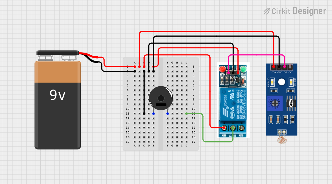
This circuit consists of a 9V battery, a 5V relay, an LDR (Light Dependent Resistor), and a Piezo Buzzer. The circuit is designed to use the LDR to control the relay, which in turn controls the Piezo Buzzer. When the LDR detects a certain level of light, it triggers the relay, which then activates the Piezo Buzzer.
Component List
9V Battery
- Description: Provides the primary power source for the circuit.
- Pins: +, -
5V Relay
- Description: Acts as a switch that is controlled by the LDR to activate the Piezo Buzzer.
- Pins: Normally Open, Common terminal, Normally Closed, In, GND, VCC
LDR (Light Dependent Resistor)
- Description: Senses the ambient light level and sends a signal to the relay.
- Pins: A0, D0, GND, VCC
Piezo Buzzer
- Description: Emits sound when activated by the relay.
- Pins: pin 1, pin 2
Wiring Details
9V Battery
+ is connected to:
- VCC of LDR
- Normally Open of 5V Relay
- VCC of 5V Relay
- is connected to:
- GND of LDR
- pin 1 of Piezo Buzzer
- GND of 5V Relay
5V Relay
Normally Open is connected to:
-
- of 9V Battery
-
Common terminal is connected to:
- pin 2 of Piezo Buzzer
Normally Closed is not connected.
In is connected to:
- D0 of LDR
GND is connected to:
-
- of 9V Battery
- GND of LDR
- pin 1 of Piezo Buzzer
-
VCC is connected to:
-
- of 9V Battery
-
LDR
VCC is connected to:
-
- of 9V Battery
-
D0 is connected to:
- In of 5V Relay
GND is connected to:
-
- of 9V Battery
- pin 1 of Piezo Buzzer
- GND of 5V Relay
-
A0 is not connected.
Piezo Buzzer
pin 1 is connected to:
- GND of LDR
-
- of 9V Battery
- GND of 5V Relay
pin 2 is connected to:
- Common terminal of 5V Relay
Code
There is no microcontroller code provided for this circuit.