Cirkit Designer
Your all-in-one circuit design IDE
Home /
Project Documentation
ESP32-Based Accident Detection and GPS Tracking System with GSM Notification
Circuit Documentation
Summary
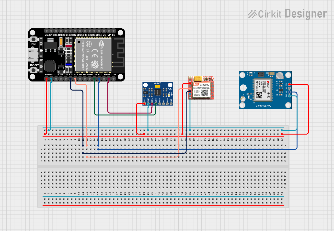
This document provides a detailed overview of a circuit designed for accident detection and location tracking. The circuit integrates an MPU6050 accelerometer, a Neo 6M GPS module, an ESP32 microcontroller, and a SIM800L GSM module. The ESP32 microcontroller serves as the central unit, interfacing with the other components to detect accidents, determine the location, and send notifications via SMS.
Component List
InvenSense MPU6050
- Description: 6-axis MotionTracking device that combines a 3-axis gyroscope and a 3-axis accelerometer.
- Pins: VCC, GND, SCL, SDA, XDA, XCL, AD0, INT
Neo 6M GPS Module
- Description: GPS module used for location tracking.
- Pins: GND, TX, RX, VCC
ESP32 (30 pin)
- Description: A powerful microcontroller with built-in Wi-Fi and Bluetooth capabilities.
- Pins: EN, VP, VN, D34, D35, D32, D33, D25, D26, D27, D14, D12, D13, GND, Vin, D23, D22, TX0, RX0, D21, D19, D18, D5, TX2, RX2, D4, D2, D15, 3V3
SIM800L
- Description: GSM module used for sending SMS notifications.
- Pins: NFT, RING, VCC, DTR, RST, MIC +, RXD, MIC-, TXD, SPK+, GND, SPK-
Wiring Details
InvenSense MPU6050
- VCC: Connected to ESP32 (30 pin) 3V3
- GND: Connected to ESP32 (30 pin) GND
- SCL: Connected to ESP32 (30 pin) D22
- SDA: Connected to ESP32 (30 pin) D21
Neo 6M GPS Module
- VCC: Connected to ESP32 (30 pin) 3V3
- GND: Connected to ESP32 (30 pin) GND
- TX: Connected to ESP32 (30 pin) RX0
ESP32 (30 pin)
- 3V3: Connected to InvenSense MPU6050 VCC, SIM800L VCC, Neo 6M GPS Module VCC
- GND: Connected to InvenSense MPU6050 GND, SIM800L GND, Neo 6M GPS Module GND
- RX2: Connected to SIM800L TXD
- TX2: Connected to SIM800L RXD
- RX0: Connected to Neo 6M GPS Module TX
- D22: Connected to InvenSense MPU6050 SCL
- D21: Connected to InvenSense MPU6050 SDA
SIM800L
- VCC: Connected to ESP32 (30 pin) 3V3
- GND: Connected to ESP32 (30 pin) GND
- TXD: Connected to ESP32 (30 pin) RX2
- RXD: Connected to ESP32 (30 pin) TX2
Documented Code
InvenSense MPU6050
// Pseudo code for accident detection
if (abs(acceleration.x) > threshold || abs(acceleration.y) > threshold || abs(acceleration.z) > threshold) {
    accident_detected = true;
}
Neo 6M GPS Module
double calculateDistance(lat1, lon1, lat2, lon2) {
    // Implement Haversine formula to calculate distance
    double dLat = (lat2 - lat1) * DEG_TO_RAD;
    double dLon = (lon2 - lon1) * DEG_TO_RAD;
    // Compute the distance using earth radius and return value
    return distance;
}
ESP32 (30 pin)
#include <Wire.h>
#include <Adafruit_MPU6050.h>
#include <Adafruit_Sensor.h>
#include <TinyGPS++.h>
#include <HardwareSerial.h>
#include <HTTPClient.h>

// GPS Module
TinyGPSPlus gps;
HardwareSerial gpsSerial(1); // Use UART1 for GPS

// MPU6050 Accelerometer
Adafruit_MPU6050 mpu;

// GSM Module
HardwareSerial gsmSerial(2); // Use UART2 for GSM
const char* apn = "your_apn"; // Replace with your APN
const char* user = "your_user"; // Replace with your APN username
const char* pass = "your_pass"; // Replace with your APN password
const char* phone_number = "916309479746"; // Replace with the recipient's phone number

void setup() {
  Serial.begin(115200);

  // Initialize GPS
  gpsSerial.begin(9600, SERIAL_8N1, 16, 17); // RX, TX pins for GPS
  Serial.println("GPS module initialized");

  // Initialize MPU6050
  if (!mpu.begin()) {
    Serial.println("Failed to find MPU6050 chip");
    while (1) {
      delay(10);
    }
  }
  Serial.println("MPU6050 initialized");
  mpu.setAccelerometerRange(MPU6050_RANGE_8_G);
  mpu.setGyroRange(MPU6050_RANGE_500_DEG);
  mpu.setFilterBandwidth(MPU6050_BAND_21_HZ);

  // Initialize GSM
  gsmSerial.begin(9600, SERIAL_8N1, 26, 27); // RX, TX pins for GSM
  Serial.println("GSM module initialized");

  // Connect to GSM network
  connectGSM();
}

void loop() {
  // Read GPS data
  while (gpsSerial.available() > 0) {
    gps.encode(gpsSerial.read());
  }

  if (gps.location.isUpdated()) {
    Serial.print("Latitude: ");
    Serial.println(gps.location.lat(), 6);
    Serial.print("Longitude: ");
    Serial.println(gps.location.lng(), 6);
  }

  // Read accelerometer data
  sensors_event_t a, g, temp;
  mpu.getEvent(&a, &g, &temp);

  // Check for fall detection (example threshold)
  if (a.acceleration.z < -9.0) {
    Serial.println("Fall detected!");
    sendSMS("Fall detected! Location: " + String(gps.location.lat(), 6) + ", " + String(gps.location.lng(), 6));
  }

  delay(1000);
}

void connectGSM() {
  gsmSerial.println("AT");
  delay(1000);
  gsmSerial.println("AT+CPIN?");
  delay(1000);
  gsmSerial.println("AT+CREG?");
  delay(1000);
  gsmSerial.println("AT+CGATT?");
  delay(1000);
  gsmSerial.println("AT+CSTT=\"" + String(apn) + "\",\"" + String(user) + "\",\"" + String(pass) + "\"");
  delay(1000);
  gsmSerial.println("AT+CIICR");
  delay(1000);
  gsmSerial.println("AT+CIFSR");
  delay(1000);
}

void sendSMS(String message) {
  gsmSerial.println("AT+CMGF=1"); // Set SMS to text mode
  delay(1000);
  gsmSerial.println("AT+CMGS=\"" + String(phone_number) + "\"");
  delay(1000);
  gsmSerial.print(message);
  delay(1000);
  gsmSerial.write(26); // ASCII code for CTRL+Z to send the SMS
  delay(1000);
}
SIM800L
gsm.sendSMS("+1234567890", "Accident Detected! Location: https://maps.google.com/?q=" + String(latitude) + "," + String(longitude));