
Arduino UNO-Based Smart Home Automation System with Bluetooth and Sensor Integration
View and Edit Project In Cirkit Designer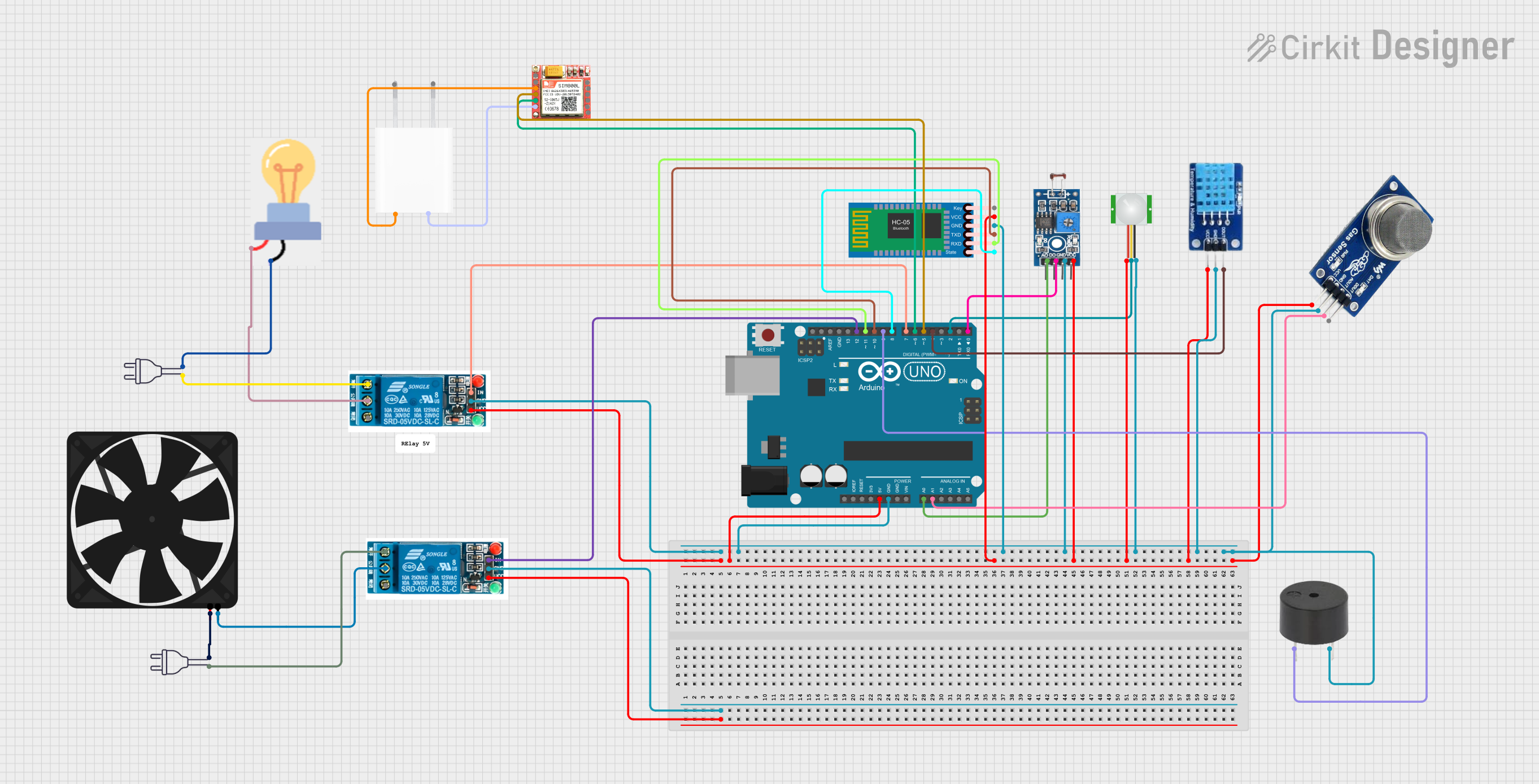
Circuit Documentation
Summary
This circuit is designed to monitor environmental conditions such as light intensity, temperature, humidity, smoke, and motion. It uses an Arduino UNO microcontroller to process sensor data and control actuators like a relay, buzzer, and fan. The circuit also includes Bluetooth and GSM modules for wireless communication.
Component List
Power 220V
- Description: Provides 220V AC power.
- Pins: Hot wire, Neutral wire
Photosensitive Sensor Module Digital Light Intensity Detection
- Description: Detects light intensity.
- Pins: Analog Output, Digital Output, Ground, VCC
MQ2
- Description: Gas and smoke sensor.
- Pins: VCC, GND, AOUT, DOUT
Buzzer
- Description: Emits sound when activated.
- Pins: PIN, GND
Bulb
- Description: Light bulb.
- Pins: GND, Power
5V Relay
- Description: Relay module for switching high voltage devices.
- Pins: Normally Open, Common terminal, Normally Closed, In, GND, VCC
Arduino UNO
- Description: Microcontroller board.
- Pins: UNUSED, IOREF, Reset, 3.3V, 5V, GND, Vin, A0, A1, A2, A3, A4, A5, SCL, SDA, AREF, D13, D12, D11, D10, D9, D8, D7, D6, D5, D4, D3, D2, D1, D0
Fan
- Description: Cooling fan.
- Pins: GND, 5V
PIR Sensor
- Description: Motion detection sensor.
- Pins: VDD, SIG, GND
DHT11
- Description: Temperature and humidity sensor.
- Pins: DATA, GND, VCC
HC-05 Bluetooth Module
- Description: Bluetooth communication module.
- Pins: Key, VCC, GND, TXD, RXD, State
SIM 800L
- Description: GSM module for cellular communication.
- Pins: NFT, RING, VCC, DTR, RST, MIC +, RXD, MIC-, TXD, SPK+, GND, SPK-
5V Adapter
- Description: Converts AC to 5V DC.
- Pins: AC In 1, AC In 2, 5V, GND
Wiring Details
Power 220V
- Hot wire: Connected to Normally Open pin of 5V relay.
- Neutral wire: Connected to GND pin of the bulb and 5V pin of the fan.
Photosensitive Sensor Module Digital Light Intensity Detection
- Analog Output: Connected to A0 pin of Arduino UNO.
- Digital Output: Connected to D0 pin of Arduino UNO.
- Ground: Connected to GND pin of Arduino UNO.
- VCC: Connected to 5V pin of Arduino UNO.
MQ2
- VCC: Connected to 5V pin of Arduino UNO.
- GND: Connected to GND pin of Arduino UNO.
- AOUT: Connected to A1 pin of Arduino UNO.
- DOUT: Not connected.
Buzzer
- PIN: Connected to D9 pin of Arduino UNO.
- GND: Connected to GND pin of Arduino UNO.
Bulb
- GND: Connected to neutral wire of power 220V.
- Power: Connected to Common terminal of 5V relay.
5V Relay (First Instance)
- Normally Open: Connected to hot wire of power 220V.
- Common terminal: Connected to power pin of the bulb.
- Normally Closed: Not connected.
- In: Connected to D7 pin of Arduino UNO.
- GND: Connected to GND pin of Arduino UNO.
- VCC: Connected to 5V pin of Arduino UNO.
5V Relay (Second Instance)
- Normally Open: Connected to hot wire of power 220V.
- Common terminal: Connected to GND pin of the fan.
- Normally Closed: Not connected.
- In: Connected to D12 pin of Arduino UNO.
- GND: Not connected.
- VCC: Not connected.
Arduino UNO
- 5V: Connected to VCC pins of various sensors and modules.
- GND: Connected to GND pins of various sensors and modules.
- A0: Connected to Analog Output pin of Photosensitive Sensor Module.
- A1: Connected to AOUT pin of MQ2.
- D0: Connected to Digital Output pin of Photosensitive Sensor Module.
- D2: Connected to SIG pin of PIR sensor.
- D4: Connected to DATA pin of DHT11.
- D5: Connected to RXD pin of SIM 800L.
- D6: Connected to TXD pin of SIM 800L.
- D7: Connected to In pin of first 5V relay.
- D8: Connected to State pin of HC-05 Bluetooth Module.
- D9: Connected to PIN of buzzer.
- D10: Connected to TXD pin of HC-05 Bluetooth Module.
- D11: Connected to RXD pin of HC-05 Bluetooth Module.
- D12: Connected to In pin of second 5V relay.
Fan
- GND: Connected to Common terminal of second 5V relay.
- 5V: Connected to neutral wire of power 220V.
PIR Sensor
- VDD: Connected to VCC pin of Arduino UNO.
- SIG: Connected to D2 pin of Arduino UNO.
- GND: Connected to GND pin of Arduino UNO.
DHT11
- DATA: Connected to D4 pin of Arduino UNO.
- GND: Connected to GND pin of Arduino UNO.
- VCC: Connected to 5V pin of Arduino UNO.
HC-05 Bluetooth Module
- Key: Not connected.
- VCC: Connected to 5V pin of Arduino UNO.
- GND: Connected to GND pin of Arduino UNO.
- TXD: Connected to D11 pin of Arduino UNO.
- RXD: Connected to D10 pin of Arduino UNO.
- State: Connected to D8 pin of Arduino UNO.
SIM 800L
- TXD: Connected to D6 pin of Arduino UNO.
- RXD: Connected to D5 pin of Arduino UNO.
- RST: Connected to 5V pin of 5V Adapter.
- GND: Connected to GND pin of 5V Adapter.
5V Adapter
- AC In 1: Not connected.
- AC In 2: Not connected.
- 5V: Connected to RST pin of SIM 800L.
- GND: Connected to GND pin of SIM 800L.
Documented Code
#include <SoftwareSerial.h>
#include <DHT.h>

#define MP2pin A1    // Cảm biến MQ-2 nối vào cổng A1
#define buzzerPin 9  // Buzzer nối vào cổng digital D9

// Khai báo chân và loại cảm biến nhiệt độ
#define DHTPIN 4       // Chân DATA của cảm biến nhiệt
#define DHTTYPE DHT11  // Loại cảm biến: DHT11 hoặc DHT22
DHT dht(DHTPIN, DHTTYPE);

// Khai báo chân cảm biến
const int lightSensorPin = A0;  // Chân cảm biến ánh sáng
const int motionSensorPin = 2;  // Chân cảm biến chuyển động
const int relayFanPin = 6;      // Chân relay điều khiển quạt
const int relayLightPin = 7;    // Chân relay điều khiển đèn

float smokeValue;  // Biến để lưu giá trị cảm biến khói

// Chân trạng thái kết nối Bluetooth
const int bluetoothStatePin = 8;

// Khai báo SoftwareSerial cho HC-05
SoftwareSerial Bluetooth(10, 11);  // RX, TX

// Biến trạng thái
bool bluetoothConnected = false;
bool fanState = false;    // Trạng thái quạt
bool lightState = false;  // Trạng thái đèn

void setup() {
  // Khởi tạo cảm biến
  pinMode(motionSensorPin, INPUT);
  pinMode(relayFanPin, OUTPUT);
  pinMode(relayLightPin, OUTPUT);
  pinMode(bluetoothStatePin, INPUT);
  pinMode(buzzerPin, OUTPUT);

  // Tắt quạt và đèn ban đầu
  digitalWrite(relayFanPin, LOW);
  digitalWrite(relayLightPin, LOW);

  // Khởi tạo giao tiếp
  Serial.begin(9600);
  Bluetooth.begin(9600);

  // Khởi tạo cảm biến nhiệt
  dht.begin();

  Serial.println