
Solar-Powered ESP32 Light-Tracking System with Servo Control
View and Edit Project In Cirkit Designer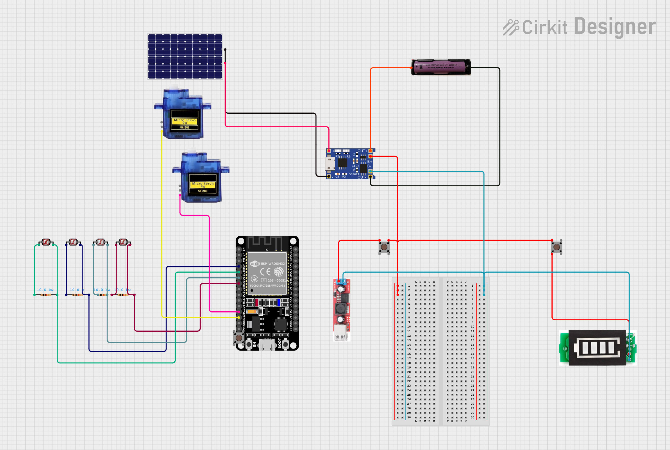
Circuit Documentation
Summary
This circuit is designed to read values from four Light Dependent Resistors (LDRs) connected to an ESP32 microcontroller and adjust two micro servos based on the light intensity detected by the LDRs. Additionally, it reads the battery voltage and prints it to the serial monitor. The circuit is powered by a 3.7V battery, which is charged using a solar panel through a TP4056 charging module. A step-down converter is used to provide a stable 5V supply for the servos and other components.
Component List
Solar Panel
- Pins: +, -
- Description: Converts sunlight into electrical energy.
- Purpose: Provides power to charge the battery.
Micro Servo 9G
- Pins: GND, +5V, PWM
- Description: Small servo motor.
- Purpose: Adjusts position based on LDR readings.
Photocell (LDR)
- Pins: pin 0, pin 1
- Description: Light-dependent resistor.
- Purpose: Detects light intensity.
Resistor
- Pins: pin1, pin2
- Description: Resistor with various resistance values.
- Purpose: Used in voltage divider circuits with LDRs.
- Properties:
- Resistance: 10 Ohms
- Resistance: 10000 Ohms
Battery Indicator
- Pins: +, -
- Description: Indicates battery status.
- Purpose: Displays battery charge level.
TP4056
- Pins: OUT-, B-, B+, OUT+, IN-, IN+
- Description: Lithium battery charging module.
- Purpose: Manages charging of the 3.7V battery.
3.7V Battery
- Pins: +, -
- Description: Rechargeable lithium battery.
- Purpose: Provides power to the circuit.
Step Down 5V Converter
- Pins: +, -
- Description: Converts higher voltage to 5V.
- Purpose: Provides stable 5V supply.
ESP32 (30 pin)
- Pins: EN, VP, VN, D34, D35, D32, D33, D25, D26, D27, D14, D12, D13, GND, Vin, D23, D22, TX0, RX0, D21, D19, D18, D5, TX2, RX2, D4, D2, D15, 3V3
- Description: Microcontroller with Wi-Fi and Bluetooth capabilities.
- Purpose: Controls the servos and reads LDR values.
Pushbutton
- Pins: Pin 3 (out), Pin 4 (out), Pin 1 (in), Pin 2 (in)
- Description: Mechanical switch.
- Purpose: User input for various functions.
Wiring Details
Solar Panel
- + connected to TP4056 IN+
- - connected to TP4056 IN-
Micro Servo 9G (Servo 1)
- GND connected to GND
- +5V connected to 5V supply
- PWM connected to ESP32 D12
Micro Servo 9G (Servo 2)
- GND connected to GND
- +5V connected to 5V supply
- PWM connected to ESP32 D13
Photocell (LDR) 1
- pin 0 connected to Resistor pin1
- pin 1 connected to ESP32 D34 and Resistor pin2
Photocell (LDR) 2
- pin 0 connected to Resistor pin1
- pin 1 connected to ESP32 D32 and Resistor pin2
Photocell (LDR) 3
- pin 0 connected to Resistor pin1
- pin 1 connected to ESP32 D35 and Resistor pin2
Photocell (LDR) 4
- pin 0 connected to Resistor pin1
- pin 1 connected to ESP32 D33 and Resistor pin2
Resistor 1 (10 Ohms)
- pin1 connected to Photocell (LDR) 1 pin 0
- pin2 connected to Photocell (LDR) 1 pin 1 and ESP32 D34
Resistor 2 (10k Ohms)
- pin1 connected to Photocell (LDR) 2 pin 0
- pin2 connected to Photocell (LDR) 2 pin 1 and ESP32 D32
Resistor 3 (10k Ohms)
- pin1 connected to Photocell (LDR) 3 pin 0
- pin2 connected to Photocell (LDR) 3 pin 1 and ESP32 D35
Resistor 4 (10k Ohms)
- pin1 connected to Photocell (LDR) 4 pin 0
- pin2 connected to Photocell (LDR) 4 pin 1 and ESP32 D33
Battery Indicator
- + connected to Pushbutton Pin 2 (in)
- - connected to TP4056 B-
TP4056
- OUT+ connected to 3.7V Battery +
- OUT- connected to 3.7V Battery -
- B+ connected to Pushbutton Pin 3 (out)
- B- connected to Step Down 5V - and Battery Indicator -
- IN+ connected to Solar Panel +
- IN- connected to Solar Panel -
3.7V Battery
- + connected to TP4056 OUT+
- - connected to TP4056 OUT-
Step Down 5V Converter
- + connected to Pushbutton Pin 1 (in)
- - connected to TP4056 B-
ESP32 (30 pin)
- D12 connected to Micro Servo 9G (Servo 1) PWM
- D13 connected to Micro Servo 9G (Servo 2) PWM
- D34 connected to Photocell (LDR) 1 pin 1 and Resistor pin2
- D32 connected to Photocell (LDR) 2 pin 1 and Resistor pin2
- D35 connected to Photocell (LDR) 3 pin 1 and Resistor pin2
- D33 connected to Photocell (LDR) 4 pin 1 and Resistor pin2
Pushbutton 1
- Pin 3 (out) connected to TP4056 B+
- Pin 1 (in) connected to Step Down 5V +
Pushbutton 2
- Pin 2 (in) connected to Battery Indicator +
Pushbutton 3
- Pin 1 (in) connected to Step Down 5V +
Code Documentation
/*
 * This code reads values from four LDRs connected to the ESP32 and adjusts two
 * servos based on the light intensity detected by the LDRs. It also reads the
 * battery voltage and prints it to the serial monitor.
 */

#include <ESP32Servo.h>

Servo myservo1, myservo2;

// Pin LDR (Light Dependent Resistors)
const int LDR1 = 34; // GPIO34 (A0 pada ESP32)
const int LDR2 = 35; // GPIO35
const int LDR3 = 32; // GPIO32
const int LDR4 = 33; // GPIO33

// Pin untuk voltmeter (baca tegangan baterai)
const int BATTERY_PIN = 36; // GPIO36 (VP)

// Variabel LDR
int rRDL1 = 0, rRDL2 = 0, rRDL3 = 0, rRDL4 = 0;
int max1 = 0, max2 = 0, max3 = 0;
const int THRESHOLD = 5; // Threshold untuk menghindari jitter

// Variabel Servo
int ser1 = 0, ser2 = 0;

// Tegangan baterai
float batteryVoltage = 0.0;
const float VOLTAGE_DIVIDER_RATIO = 2.0; // Rasio tegangan resistor divider

void setup() {
  // Attach servo ke pin GPIO ESP32
  myservo1.attach(13); // GPIO13
  myservo2.attach(12); // GPIO12

  // In