
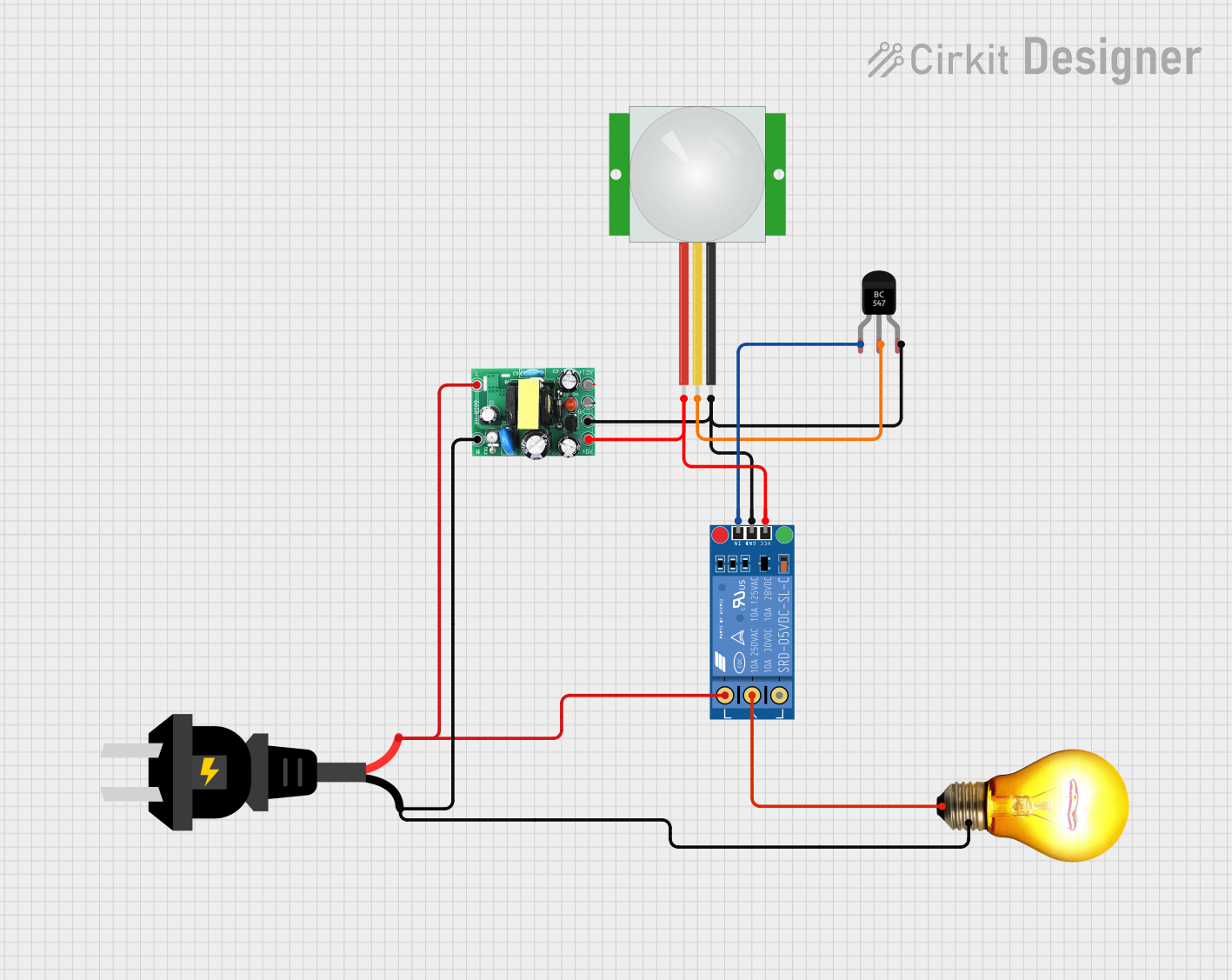
Circuit Documentation
Summary
This document provides a detailed overview of a circuit designed to control an AC bulb using a PIR sensor, a relay, and a transistor. The circuit converts AC to DC using an AC to DC converter and uses a PIR sensor to detect motion, which then triggers a relay through a transistor to turn on the AC bulb.
Component List
PIR Sensor
- Pins: VDD, SIG, GND
- Description: Passive Infrared Sensor used to detect motion.
- Purpose in Circuit: Detects motion and sends a signal to the transistor.
KF-301 Relay
- Pins: signal, power, ground, NC, C, NO
- Description: Electromechanical relay.
- Purpose in Circuit: Controls the AC bulb based on the signal received from the transistor.
BC547 Transistor
- Pins: Collector, Base, Emitter
- Description: NPN Bipolar Junction Transistor.
- Purpose in Circuit: Acts as a switch to control the relay based on the signal from the PIR sensor.
AC to DC Converter (actodc)
- Pins: 12v, -, 5v, live, neutral
- Description: Converts AC voltage to DC voltage.
- Purpose in Circuit: Provides the necessary DC power for the PIR sensor, relay, and transistor.
AC Source
- Pins: +, -
- Description: AC power supply.
- Purpose in Circuit: Provides AC power to the AC to DC converter and the AC bulb.
AC Bulb
- Pins: P, N
- Description: Standard AC light bulb.
- Purpose in Circuit: Illuminates when the relay is activated.
Wiring Details
PIR Sensor
- VDD is connected to the 5v pin of the AC to DC Converter.
- SIG is connected to the Base pin of the BC547 Transistor.
- GND is connected to the - pin of the AC to DC Converter.
KF-301 Relay
- power is connected to the 5v pin of the AC to DC Converter.
- ground is connected to the - pin of the AC to DC Converter.
- signal is connected to the Collector pin of the BC547 Transistor.
- C is connected to the P pin of the AC Bulb.
- NO is connected to the live pin of the AC to DC Converter.
- NO is also connected to the + pin of the AC Source.
BC547 Transistor
- Base is connected to the SIG pin of the PIR Sensor.
- Collector is connected to the signal pin of the KF-301 Relay.
- Emitter is connected to the - pin of the AC to DC Converter.
AC to DC Converter (actodc)
- 5v is connected to the VDD pin of the PIR Sensor and the power pin of the KF-301 Relay.
- - is connected to the GND pin of the PIR Sensor, the ground pin of the KF-301 Relay, and the Emitter pin of the BC547 Transistor.
- live is connected to the NO pin of the KF-301 Relay and the + pin of the AC Source.
- neutral is connected to the N pin of the AC Bulb and the - pin of the AC Source.
AC Source
- + is connected to the live pin of the AC to DC Converter and the NO pin of the KF-301 Relay.
- - is connected to the neutral pin of the AC to DC Converter and the N pin of the AC Bulb.
AC Bulb
- P is connected to the C pin of the KF-301 Relay.
- N is connected to the neutral pin of the AC to DC Converter and the - pin of the AC Source.
Code
There is no microcontroller code provided for this circuit.