
Arduino UNO Controlled Servo with Relay-Activated LED and Buzzer Notification System
View and Edit Project In Cirkit Designer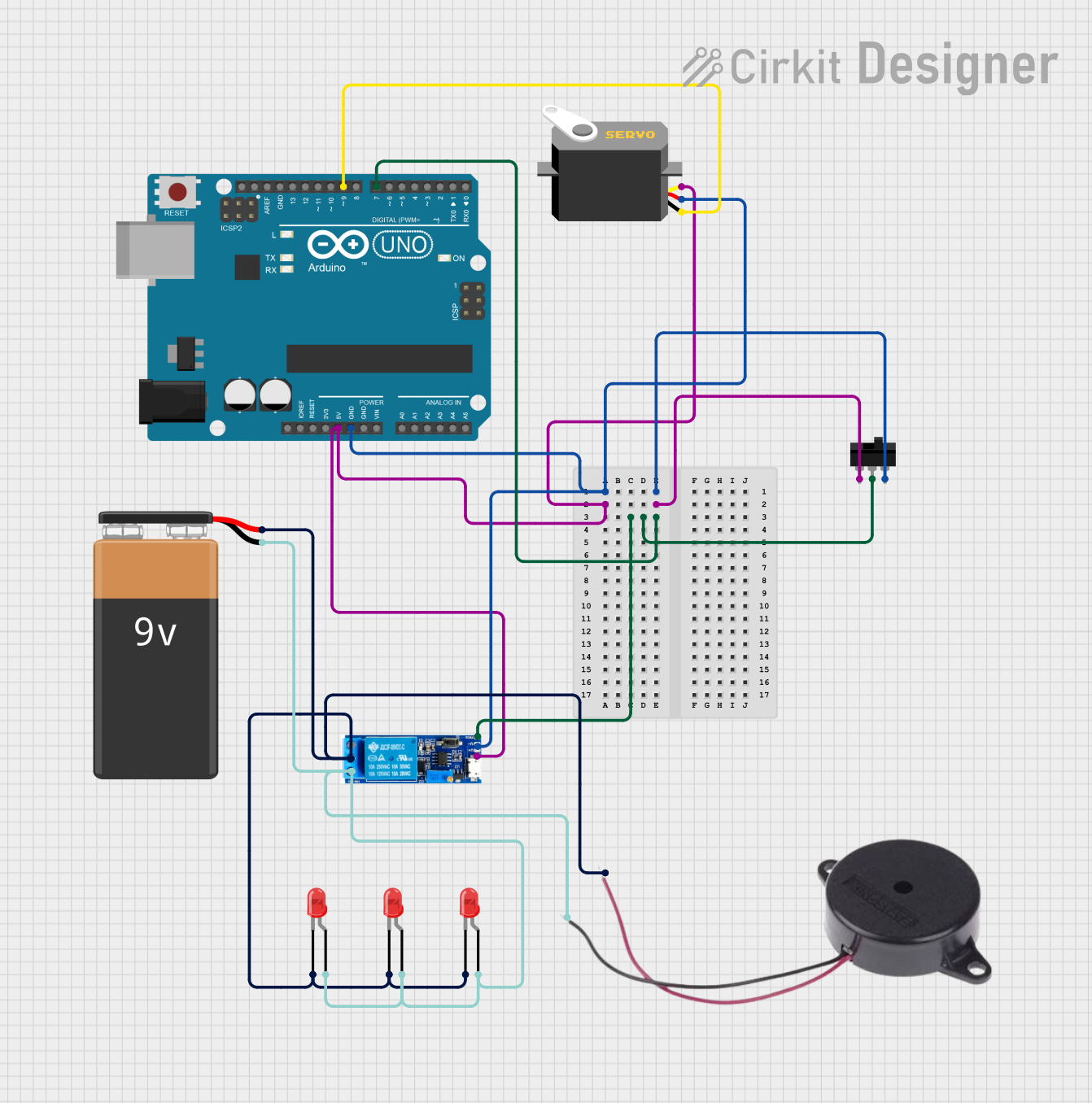
Circuit Documentation
Summary
This circuit is designed to control a servo motor using an Arduino UNO microcontroller. It includes a toggle switch to control the power flow and a relay module to manage higher power loads. The circuit also features three red LEDs and a buzzer for indication purposes, all powered by a 9V battery. The Arduino UNO is responsible for controlling the servo and potentially other logic functions as defined in the embedded code.
Component List
Arduino UNO
- Microcontroller board based on the ATmega328P
- It has 14 digital input/output pins, 6 analog inputs, a 16 MHz quartz crystal, a USB connection, a power jack, an ICSP header, and a reset button.
Servo
- A rotary actuator or linear actuator that allows for precise control of angular or linear position, velocity, and acceleration.
- It consists of a suitable motor coupled to a sensor for position feedback.
Toggle Switch
- An electrical switch that is manually actuated by a mechanical lever, handle, or rocking mechanism.
9V Battery
- A standard size of battery typically used in small electronic devices, smoke detectors, and clocks.
LED: Two Pin (red)
- A light-emitting diode that emits red light when a voltage is applied to its anode and cathode.
Buzzer
- An audio signaling device, which may be mechanical, electromechanical, or piezoelectric.
Relay module 5v-30v
- An electrically operated switch that allows you to turn on or off a circuit using voltage and/or current much higher than a microcontroller can handle.
Wiring Details
Arduino UNO
5Vconnected to the servo's pulse line, relay module V+, and toggle switch L1.GNDconnected to the servo's VCC, relay module V-, and toggle switch L2.D9connected to the servo's GND.D7connected to the relay module's trigger and toggle switch COM.
Servo
pulseconnected to Arduino UNO 5V.vccconnected to Arduino UNO GND.gndconnected to Arduino UNO D9.
Toggle Switch
L1connected to Arduino UNO 5V.COMconnected to Arduino UNO D7.L2connected to Arduino UNO GND.
9V Battery
+connected to the anodes of all three LEDs, the common contact of the relay module, and the buzzer's POSITIVE.-connected to the cathodes of all three LEDs, the normally closed contact of the relay module, and the buzzer's NEGATIVE.
LED: Two Pin (red)
anodeconnected to 9V Battery -.cathodeconnected to 9V Battery +.
Buzzer
POSITIVEconnected to 9V Battery +.NEGATIVEconnected to 9V Battery -.
Relay module 5v-30v
common contactconnected to 9V Battery +.normally opennot connected in this circuit.normally closedconnected to 9V Battery -.triggerconnected to Arduino UNO D7.V-connected to Arduino UNO GND.V+connected to Arduino UNO 5V.
Documented Code
Arduino UNO Code (sketch.ino)
void setup() {
  // put your setup code here, to run once:

}

void loop() {
  // put your main code here, to run repeatedly:

}
Additional Documentation (documentation.txt)
No additional documentation provided in the code input.