
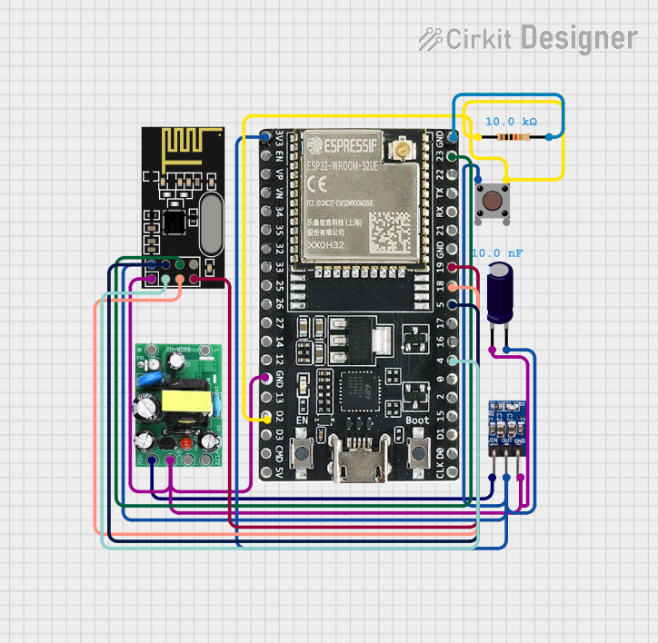
Circuit Documentation
Summary
This circuit integrates an ESP32-WROOM-32UE microcontroller with an NRF24L01 wireless transceiver module, a pushbutton, an AMS1117 3.3V voltage regulator, an electrolytic capacitor, a resistor, and an AC-DC PSU board that converts 220V AC to 5V & 12V DC. The ESP32 microcontroller serves as the central processing unit, interfacing with the NRF24L01 for wireless communication. The pushbutton is used as an input device, potentially for triggering events or actions. The AMS1117 3.3V regulator, along with the electrolytic capacitor, ensures a stable 3.3V supply for the NRF24L01 and the ESP32's 3.3V pin. The resistor is used to form a pull-up or pull-down for the pushbutton. The AC-DC PSU board provides the necessary power to the circuit.
Component List
ESP32-WROOM-32UE
- Description: A powerful microcontroller with Wi-Fi and Bluetooth capabilities.
- Pins: 3v3, EN, VP, VN, 34, 35, 32, 33, 25, 26, 27, 14, 12, GND, 13, D2, D3, 5V, 23, 22, TX, RX, 21, 19, 18, 5, 17, 16, 4, 0, 2, 15, D1, D0, CKL
NRF24L01
- Description: A 2.4GHz wireless transceiver module.
- Pins: IRQ (not used), MOSI, CSN, VCC (3V), GND, CE, SCK, MISO
Pushbutton
- Description: A simple pushbutton switch.
- Pins: Pin 3 (out), Pin 4 (out), Pin 1 (in), Pin 2 (in)
AMS1117 3.3
- Description: A low dropout voltage regulator that outputs 3.3V.
- Pins: VIN, OUT, GND
Electrolytic Capacitor
- Description: A capacitor used for filtering and stabilizing the voltage supply.
- Pins: -, +
- Properties: Capacitance - 10nF (1e-8 Farads)
Resistor
- Description: A resistor used to limit current or voltage levels within the circuit.
- Pins: pin1, pin2
- Properties: Resistance - 10k Ohms
AC-DC PSU board 220V-5V&12V
- Description: A power supply unit that converts 220V AC to 5V & 12V DC.
- Pins: AC-N, AC-L, +5V, GND, +12V
Wiring Details
ESP32-WROOM-32UE
- 3v3 connected to AMS1117 3.3 (OUT), NRF24L01 (VCC), and Electrolytic Capacitor (+)
- GND connected to AMS1117 3.3 (GND), NRF24L01 (GND), AC-DC PSU board (GND), and Resistor (pin2)
- D2 connected to Pushbutton (Pin 3)
- 23 (MOSI) connected to NRF24L01 (MOSI)
- 19 (MISO) connected to NRF24L01 (MISO)
- 18 (SCK) connected to NRF24L01 (SCK)
- 5 (CSN) connected to NRF24L01 (CSN)
- 4 (CE) connected to NRF24L01 (CE)
NRF24L01
- VCC connected to AMS1117 3.3 (OUT) and Electrolytic Capacitor (+)
- GND connected to AMS1117 3.3 (GND) and AC-DC PSU board (GND)
- MOSI connected to ESP32-WROOM-32UE (23)
- MISO connected to ESP32-WROOM-32UE (19)
- SCK connected to ESP32-WROOM-32UE (18)
- CSN connected to ESP32-WROOM-32UE (5)
- CE connected to ESP32-WROOM-32UE (4)
Pushbutton
- Pin 1 connected to AMS1117 3.3 (OUT) and Electrolytic Capacitor (+)
- Pin 3 connected to Resistor (pin1) and ESP32-WROOM-32UE (D2)
AMS1117 3.3
- VIN connected to AC-DC PSU board (+5V)
- OUT connected to Pushbutton (Pin 1), Electrolytic Capacitor (+), and NRF24L01 (VCC)
- GND connected to Electrolytic Capacitor (-), NRF24L01 (GND), and AC-DC PSU board (GND)
Electrolytic Capacitor
-
- connected to AMS1117 3.3 (OUT), NRF24L01 (VCC), and Pushbutton (Pin 1)
-
- connected to AMS1117 3.3 (GND) and AC-DC PSU board (GND)
Resistor
- pin1 connected to Pushbutton (Pin 3)
- pin2 connected to ESP32-WROOM-32UE (GND)
AC-DC PSU board 220V-5V&12V
- +5V connected to AMS1117 3.3 (VIN)
- GND connected to AMS1117 3.3 (GND), NRF24L01 (GND), and Electrolytic Capacitor (-)
Documented Code
No code has been provided for the microcontroller. When code is available, it should be documented here with explanations for each function and routine, including setup and loop functions, interrupt service routines, and any communication protocols implemented for interfacing with the NRF24L01 module.