
Circuit Documentation
Summary
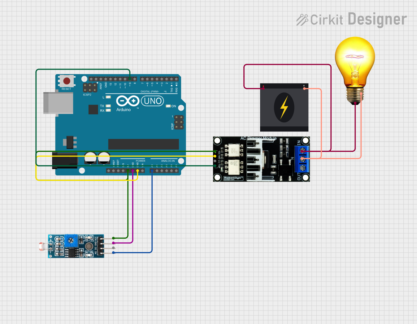
This circuit is designed to control the brightness of an AC bulb using an Arduino UNO and an AC Dimmer Lamp Module. The brightness is adjusted based on the ambient light level detected by an LDR (Light Dependent Resistor) module. The Arduino reads the LDR value and adjusts the dimmer module accordingly to control the AC bulb's brightness.
Component List
AC Dimmer Lamp Module
- Description: A module used to control the brightness of an AC lamp.
- Pins: VCC, GND, Z-C, PWM, N, L
Arduino UNO
- Description: A microcontroller board based on the ATmega328P.
- Pins: UNUSED, IOREF, Reset, 3.3V, 5V, GND, Vin, A0, A1, A2, A3, A4, A5, SCL, SDA, AREF, D13, D12, D11, D10, D9, D8, D7, D6, D5, D4, D3, D2, D1, D0
AC Bulb
- Description: A standard AC bulb.
- Pins: P, N
Module LDR
- Description: A module that includes a Light Dependent Resistor to measure ambient light levels.
- Pins: VCC, GND, DO, AO
240v Power Source
- Description: A standard 240V AC power source.
- Pins: Live, Neutral
Wiring Details
AC Dimmer Lamp Module
- VCC: Connected to 5V on Arduino UNO and VCC on Module LDR
- GND: Connected to GND on Arduino UNO
- PWM: Connected to D9 on Arduino UNO
- N: Connected to Neutral on 240v Power Source and N on AC Bulb
- L: Connected to Live on 240v Power Source and P on AC Bulb
Arduino UNO
- 5V: Connected to VCC on AC Dimmer Lamp Module and VCC on Module LDR
- GND: Connected to GND on AC Dimmer Lamp Module and GND on Module LDR
- D9: Connected to PWM on AC Dimmer Lamp Module
- A0: Connected to AO on Module LDR
AC Bulb
- P: Connected to Live on 240v Power Source and L on AC Dimmer Lamp Module
- N: Connected to Neutral on 240v Power Source and N on AC Dimmer Lamp Module
Module LDR
- VCC: Connected to 5V on Arduino UNO and VCC on AC Dimmer Lamp Module
- GND: Connected to GND on Arduino UNO
- AO: Connected to A0 on Arduino UNO
240v Power Source
- Live: Connected to L on AC Dimmer Lamp Module and P on AC Bulb
- Neutral: Connected to N on AC Dimmer Lamp Module and N on AC Bulb
Documented Code
#define LDR_PIN A0  // Analog pin connected to LDR module AO pin
#define DIMMER_PIN 9  // PWM pin connected to Dimmer module PWM pin

void setup() {
  pinMode(DIMMER_PIN, OUTPUT);
  Serial.begin(9600);
}

void loop() {
  int ldrValue = analogRead(LDR_PIN);  // Read the LDR value (0-1023)
  Serial.print("LDR Value: ");
  Serial.println(ldrValue);

  // Map the LDR value to a PWM value (0-255)
  int pwmValue = map(ldrValue, 0, 1023, 0, 255);
  analogWrite(DIMMER_PIN, pwmValue);  // Write the PWM value to the dimmer module

  delay(100);  // Small delay to stabilize readings
}
This code reads the value from the LDR module and maps it to a PWM value to control the brightness of the AC bulb through the dimmer module. The analogRead function reads the LDR value, and the analogWrite function adjusts the dimmer module's output accordingly. The Serial functions are used for debugging purposes to print the LDR values to the serial monitor.