
Circuit Documentation
Summary
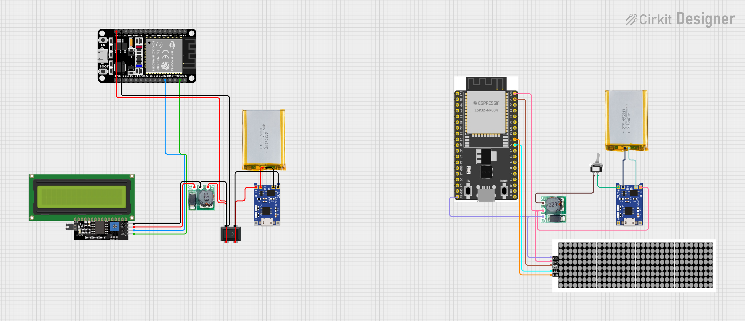
The circuit in question appears to be a power management and display system that includes a microcontroller, power supply components, a battery charging module, and display units. The microcontroller used is an ESP32, which is a versatile and powerful microcontroller with Wi-Fi capabilities. The circuit includes two power supply modules that step up the voltage from 3V to 5V, suitable for powering various components that require a 5V supply. There are also two 2000mAh batteries included, which are likely used as the primary power source for the circuit. The batteries are charged using TP4056 charging modules. For user interaction, the circuit includes an LCD display with I2C communication and an LED dot display. A toggle switch and a rocker switch are included for controlling power flow or other functions within the circuit.
Component List
LCD Display 16x4 I2C
- Description: A 16x4 character LCD display module with an I2C interface.
- Pins: SCL, SDA, VCC, GND
Step Up Boost 3v-5v
- Description: A voltage step-up (boost) converter module that increases the input voltage from 3V to 5V.
- Pins: Vi, GND, Vo
Toggle Switch SPST
- Description: A single-pole single-throw (SPST) toggle switch used for switching circuits on and off.
- Pins: L1, COM
LED DOT DISPLAY
- Description: An LED dot matrix display module for showing patterns or characters.
- Pins: VCC, GND, DIN, CS, CLK
2000mAh Battery
- Description: A rechargeable lithium-ion battery with a capacity of 2000mAh.
- Pins: VCC, GND
ESP32 Wroom Dev Kit
- Description: A development board based on the ESP32 microcontroller with a variety of GPIOs and other features.
- Pins: NOP, EN, VP, VN, GPIO 34, GPIO 35, GPIO 32, GPIO 33, GPIO 25, GPIO 26, GPIO 27, GPIO 14, GPIO 13, V5, GPIO 23, GPIO 22, TXD, RXD, GPIO 21, GND, GPIO 19, GPIO 18, GPIO 5, GPIO 17, GPIO 16, GPIO 4, GPIO 0, GPIO 15, 3V3
TP4056
- Description: A lithium battery charging module with a micro USB input.
- Pins: OUT-, B-, B+, OUT+, IN-, IN+
Rocker Switch 4 Pin
- Description: A rocker switch with four pins, typically used to control the power supply to a circuit.
- Pins: 1, 3, 2, 4
Wiring Details
LCD Display 16x4 I2C
- SCL: Connected to ESP32 (30 pin) D22
- SDA: Connected to ESP32 (30 pin) D21
- VCC: Connected to Step Up Boost 3v-5v Vo
- GND: Connected to RockerSwitch4Pin 4, ESP32 (30 pin) GND, Step Up Boost 3v-5v GND
Step Up Boost 3v-5v
- Vi: Connected to RockerSwitch4Pin 3, ESP32 (30 pin) Vin
- GND: Connected to RockerSwitch4Pin 4, ESP32 (30 pin) GND, LCD Display 16x4 I2C GND
- Vo: Connected to LCD Display 16x4 I2C VCC
Toggle Switch SPST
- L1: Connected to Step Up Boost 3v-5v Vi
- COM: Connected to TP4056 OUT+
LED DOT DISPLAY
- VCC: Connected to Step Up Boost 3v-5v Vo, ESP 32 Wroom Dev Kit V5
- GND: Connected to ESP 32 Wroom Dev Kit NOP, Step Up Boost 3v-5v GND, TP4056 OUT-
- DIN: Connected to ESP 32 Wroom Dev Kit GPIO 23
- CS: Connected to ESP 32 Wroom Dev Kit GPIO 5
- CLK: Connected to ESP 32 Wroom Dev Kit GPIO 18
2000mAh Battery
- VCC: Connected to TP4056 B+
- GND: Connected to TP4056 B-
ESP32 Wroom Dev Kit
- V5: Connected to Step Up Boost 3v-5v Vo, LED DOT DISPLAY VCC
- GND: Connected to RockerSwitch4Pin 4, LCD Display 16x4 I2C GND
- GPIO 23: Connected to LED DOT DISPLAY DIN
- GPIO 5: Connected to LED DOT DISPLAY CS
- GPIO 18: Connected to LED DOT DISPLAY CLK
TP4056
- OUT-: Connected to RockerSwitch4Pin 2, LED DOT DISPLAY GND
- B-: Connected to 2000mAh Battery GND
- B+: Connected to 2000mAh Battery VCC
- OUT+: Connected to RockerSwitch4Pin 1, Toggle Switch SPST COM
Rocker Switch 4 Pin
- 1: Connected to TP4056 OUT+
- 2: Connected to TP4056 OUT-
- 3: Connected to Step Up Boost 3v-5v Vi, ESP32 (30 pin) Vin
- 4: Connected to ESP32 (30 pin) GND, LCD Display 16x4 I2C GND, Step Up Boost 3v-5v GND
Documented Code
No code has been provided for the microcontrollers in the circuit. Therefore, this section is not applicable for the current documentation.