
Arduino-Controlled Rhino Motor Driver for Multi-Motor Robotics Platform
View and Edit Project In Cirkit Designer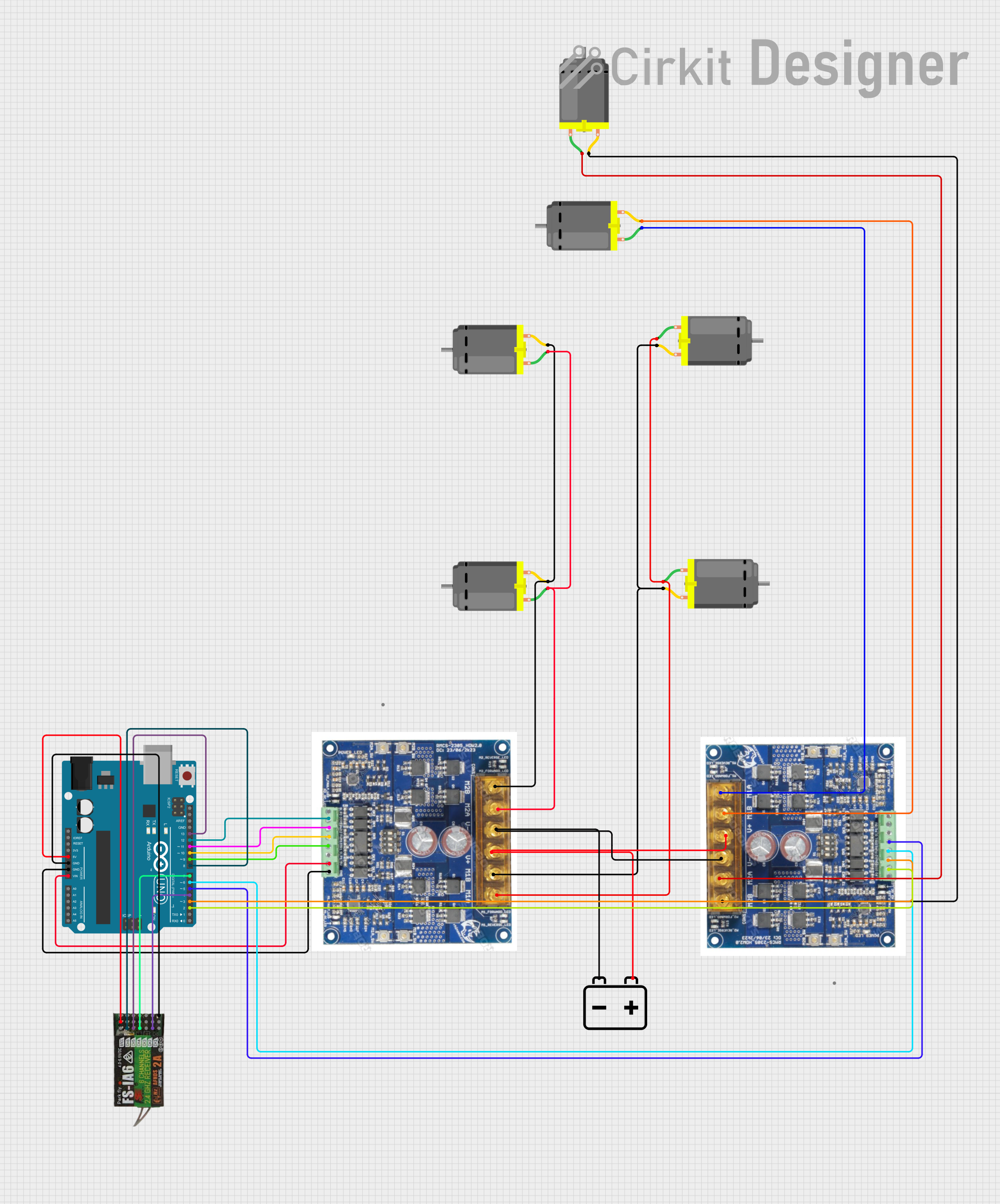
Circuit Documentation
Summary
This circuit is designed to control multiple DC motors using two Rhino motor drivers, which are interfaced with an Arduino UNO microcontroller. The Arduino UNO also interfaces with a FLYSKY FS-IA6 receiver to receive control signals. The entire system is powered by a 12V battery. The Arduino UNO's GPIO pins are used to send control signals to the motor drivers, which in turn drive the motors. The battery provides the necessary power to the motor drivers and the motors, while the Arduino and the receiver are powered by the Arduino's regulated 5V output.
Component List
Arduino UNO
- Microcontroller board based on the ATmega328P
- It has 14 digital input/output pins, 6 analog inputs, a 16 MHz quartz crystal, a USB connection, a power jack, an ICSP header, and a reset button.
Rhino Motor Driver (x2)
- A motor driver capable of driving two DC motors each.
- It has inputs for motor control signals such as direction and PWM inputs for speed control.
DC Motor (x8)
- A standard DC motor with two connection pins for driving the motor.
12V Battery
- A power source for the motors and motor drivers.
- It has a positive and a negative terminal.
FLYSKY FS-IA6 Receiver
- A 6-channel receiver for radio control applications.
- It has channels for signal input and outputs 5V and ground for power.
Wiring Details
Arduino UNO
5VandGNDare connected to the FLYSKY FS-IA6 receiver to power it.Vinis connected to the 5V input on one of the Rhino motor drivers to power the Arduino from the motor driver's regulated output.GNDis also connected to the ground of the motor drivers to establish a common ground.- Digital pins
D13,D12,D11,D10,D9,D8,D7,D6,D5,D4,D3, andD2are used to interface with the motor drivers and the FLYSKY FS-IA6 receiver for control signals.
Rhino Motor Driver
GND,5V,SLP1,DIR1,PWM1,PWM2,DIR2, andSLP2are connected to the corresponding pins on the Arduino UNO for control.V+andV-are connected to the positive and negative terminals of the 12V battery to power the motors.M1A,M1B,M2A, andM2Bare connected to the respective pins of the DC motors to drive them.
DC Motors
- Each motor has two pins (
pin 1andpin 2) that connect to the motor driver outputs.
12V Battery
- The positive terminal (
+) is connected to theV+of both Rhino motor drivers. - The negative terminal (
-) is connected to theV-of both Rhino motor drivers.
FLYSKY FS-IA6 Receiver
5VandGNDare connected to the Arduino UNO for power.- Channels
CH1,CH2,CH3,CH4,CH5, andCH6are connected to the Arduino UNO's digital pins for control signal input.
Documented Code
Arduino UNO Code (sketch.ino)
void setup() {
  // put your setup code here, to run once:

}

void loop() {
  // put your main code here, to run repeatedly:

}
Note: The provided code is a template and does not contain any functional code to control the motors or interface with the receiver. The user must implement the setup and loop functions to initialize the control pins and implement the control logic.
Additional Notes
- The
documentation.txtfile is empty and does not contain any additional information. - The circuit design and code must be further developed to achieve the desired functionality.