Cirkit Designer
Your all-in-one circuit design IDE
Home /
Project Documentation
Wi-Fi Controlled LED Indicator with Sound Sensor
Circuit Documentation
Summary
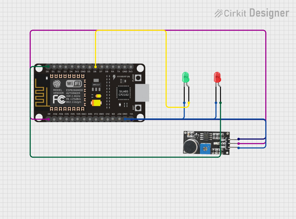
This circuit utilizes an ESP8266 NodeMCU microcontroller to interface with two LEDs (one red and one green) and a sound sensor. The red LED is activated based on a specific condition, while the green LED is controlled separately. The sound sensor detects sound levels and outputs a signal to the microcontroller, which can be used for further processing or triggering actions.
Component List
ESP8266 NodeMCU
- Description: A low-cost Wi-Fi microcontroller with GPIO pins for interfacing with various components.
- Purpose: Acts as the central control unit for the circuit, processing inputs from the sound sensor and controlling the LEDs.
LED: Two Pin (Green)
- Description: A standard two-pin green LED.
- Purpose: Provides visual feedback or indication based on the circuit's logic.
LED: Two Pin (Red)
- Description: A standard two-pin red LED.
- Purpose: Provides visual feedback or indication based on specific conditions in the circuit.
Sound Sensor
- Description: A sensor that detects sound levels and outputs a corresponding signal.
- Purpose: Monitors sound levels and sends an output signal to the microcontroller for processing.
Wiring Details
ESP8266 NodeMCU
- D0: Connected to the anode of the red LED.
- D6: Connected to the anode of the green LED.
- A0: Connected to the OUT pin of the sound sensor.
- GND: Connected to the cathode of the red LED, cathode of the green LED, and GND pin of the sound sensor.
- VIN: Connected to the 5V + pin of the sound sensor.
LED: Two Pin (Green)
- Anode: Connected to D6 of the ESP8266 NodeMCU.
- Cathode: Connected to GND of the ESP8266 NodeMCU.
LED: Two Pin (Red)
- Anode: Connected to D0 of the ESP8266 NodeMCU.
- Cathode: Connected to GND of the ESP8266 NodeMCU.
Sound Sensor
- OUT: Connected to A0 of the ESP8266 NodeMCU.
- GND: Connected to GND of the ESP8266 NodeMCU.
- 5V +: Connected to VIN of the ESP8266 NodeMCU.
Documented Code
Code File: sketch.ino
void setup() {
  // put your setup code here, to run once:

}

void loop() {
  // put your main code here, to run repeatedly:

}
Code File: documentation.txt
No additional code provided in this file.