Cirkit Designer
Your all-in-one circuit design IDE
Home /
Project Documentation
Arduino UNO IR Sensor Motion Detection System

Circuit Documentation
Summary of the Circuit
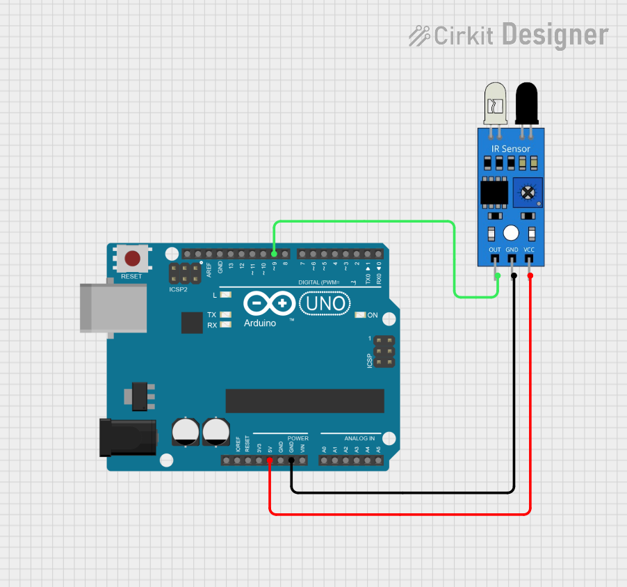
This circuit integrates an Arduino UNO with an infrared (IR) sensor to detect motion. The IR sensor's output is connected to one of the digital pins on the Arduino UNO. When motion is detected by the IR sensor, the Arduino reacts by turning off its built-in LED and printing a message to the serial monitor. Conversely, when motion is no longer detected, the Arduino turns the LED back on and prints a different message to the serial monitor. The Arduino UNO is also responsible for powering the IR sensor.
Component List
Arduino UNO
- Description: A microcontroller board based on the ATmega328P.
- Pins: UNUSED, IOREF, Reset, 3.3V, 5V, GND, Vin, A0-A5, SCL, SDA, AREF, D0-D13
- Purpose: Acts as the central processing unit for the circuit, reading the IR sensor output and controlling the built-in LED based on the sensor's signal.
IR Sensor
- Description: A sensor that detects infrared radiation, typically used for motion or proximity detection.
- Pins: out, gnd, vcc
- Purpose: Detects motion and sends a signal to the Arduino UNO.
Wiring Details
Arduino UNO
- 5V: Provides power to the IR sensor.
- GND: Common ground with the IR sensor.
- D9: Receives the output signal from the IR sensor.
IR Sensor
- VCC: Connected to the 5V output from the Arduino UNO.
- GND: Connected to the ground (GND) on the Arduino UNO.
- OUT: Sends the signal to digital pin D9 on the Arduino UNO.
Documented Code
/*
  IR Sensor Motion Detection with Arduino UNO

  This sketch is designed to use an IR sensor connected to pin D9 of an Arduino UNO
  to detect motion. When motion is detected, the built-in LED on pin D13 will turn off,
  and "Motion Detected!" will be printed to the serial monitor. When motion is no longer
  detected, the built-in LED will turn on, and "Motion Ended!" will be printed to the
  serial monitor.

  The serial communication is initiated at a baud rate of 115200 to allow for fast data
  transfer. The built-in LED is used as an indicator for motion detection status.

  Circuit connections:
  - IR sensor output to Arduino pin D9
  - IR sensor GND to Arduino GND
  - IR sensor VCC to Arduino 5V
  - Built-in LED on Arduino pin D13 (no external LED required)
*/

int IRSensor = 9; // connect IR sensor module to Arduino pin D9
int LED = 13; // use built-in LED connected to Arduino pin D13

void setup(){
  Serial.begin(115200); // Init Serial at 115200 Baud Rate.
  Serial.println("Serial Working"); // Test to check if serial is working or not
  pinMode(IRSensor, INPUT); // Set IR Sensor pin as INPUT
  pinMode(LED, OUTPUT); // Set LED Pin as OUTPUT
}

void loop(){
  int sensorStatus = digitalRead(IRSensor); // Read the IR sensor pin
  if (sensorStatus == HIGH) // Check if the pin is HIGH
  {
    digitalWrite(LED, LOW); // Turn off the built-in LED
    Serial.println("Motion Detected!"); // Print "Motion Detected!" on the serial monitor window
  }
  else {
    digitalWrite(LED, HIGH); // Turn on the built-in LED
    Serial.println("Motion Ended!"); // Print "Motion Ended!" on the serial monitor window
  }
}
This code is designed to be uploaded to the Arduino UNO microcontroller. It sets up the serial communication, configures the IR sensor and LED pins, and contains the main loop that checks the sensor status and controls the LED accordingly.