
Circuit Documentation
Summary of the Circuit
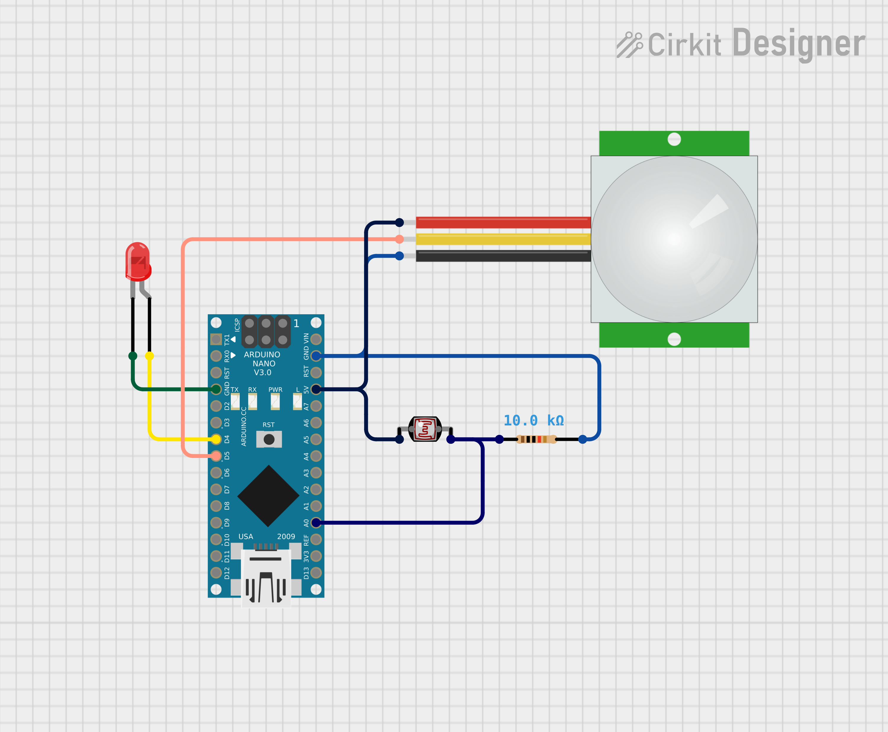
This circuit is designed to interface a PIR (Passive Infrared) sensor, a photocell (Light Dependent Resistor, LDR), and a red LED with an Arduino Nano microcontroller. The PIR sensor is used to detect motion, the photocell measures light levels, and the LED serves as an indicator. The Arduino Nano controls the behavior of the LED based on the inputs from the PIR sensor and the photocell. A resistor is included in the circuit to form a voltage divider with the photocell for analog light level sensing.
Component List
PIR Sensor
- Description: A sensor that detects motion by measuring changes in the infrared levels emitted by surrounding objects.
- Pins: VDD, SIG, GND
Photocell (LDR)
- Description: A light-sensitive device whose resistance changes with light intensity.
- Pins: pin 0, pin 1
LED: Two Pin (red)
- Description: A red light-emitting diode used as an indicator.
- Pins: cathode, anode
Arduino Nano
- Description: A small, complete, and breadboard-friendly microcontroller board based on the ATmega328P.
- Pins: D1/TX, D0/RX, RESET, GND, D2, D3, D4, D5, D6, D7, D8, D9, D10, D11/MOSI, D12/MISO, VIN, 5V, A7, A6, A5, A4, A3, A2, A1, A0, AREF, 3V3, D13/SCK
Resistor
- Description: A passive two-terminal electrical component that implements electrical resistance as a circuit element.
- Value: 10,000 Ohms (10kΩ)
- Pins: pin1, pin2
Wiring Details
PIR Sensor
- VDD: Connected to Arduino Nano 5V
- SIG: Connected to Arduino Nano D5
- GND: Connected to Arduino Nano GND
Photocell (LDR)
- pin 0: Connected to Arduino Nano 5V
- pin 1: Connected to Arduino Nano A0 through a 10kΩ resistor
LED: Two Pin (red)
- cathode: Connected to Arduino Nano GND
- anode: Connected to Arduino Nano D4
Arduino Nano
- 5V: Provides power to PIR sensor and photocell (LDR)
- D5: Receives signal from PIR sensor
- GND: Common ground for PIR sensor, LED, and one side of the resistor
- A0: Receives variable voltage from photocell and resistor voltage divider
- D4: Controls the LED
Resistor (10kΩ)
- pin1: Connected to Arduino Nano A0
- pin2: Connected to Arduino Nano GND and photocell (LDR) pin 1
Documented Code
The code for the Arduino Nano is structured with a setup() function that runs once at the start and a loop() function that runs continuously.
void setup() {
  // put your setup code here, to run once:

}

void loop() {
  // put your main code here, to run repeatedly:

}
The setup() function is used to initialize the pins as inputs or outputs and to set up any other initial conditions. The loop() function contains the main logic of the program, which will read the sensor inputs, process the data, and control the LED accordingly.
The provided code is a template and does not contain any specific logic. The user is expected to fill in the setup() and loop() functions with the desired behavior for the circuit.