Cirkit Designer
Your all-in-one circuit design IDE
Home /
Project Documentation
Arduino-Based RGB LED Color Controller with Potentiometers
Circuit Documentation
Summary
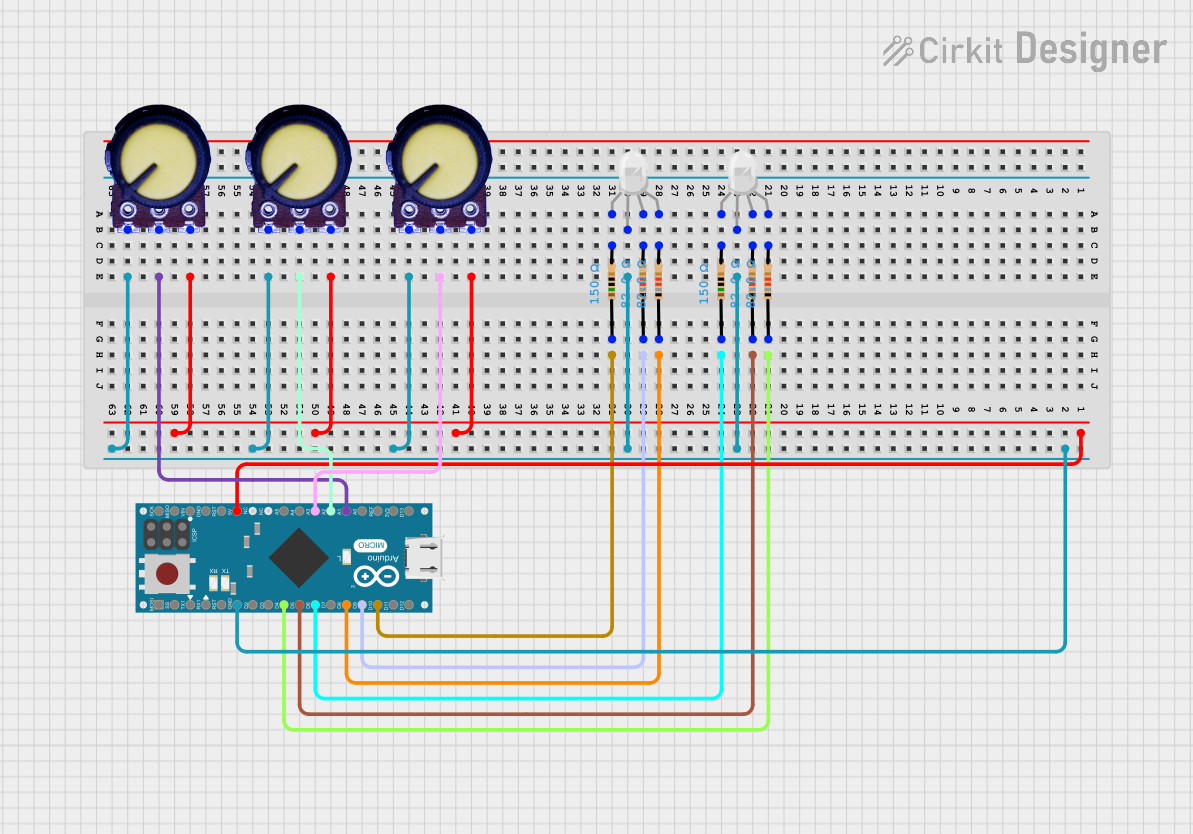
This circuit is designed to control the color of two RGB LEDs using three potentiometers. The potentiometers adjust the red, green, and blue components of the LEDs, allowing for smooth color transitions. An Arduino Micro (Rev3) microcontroller reads the potentiometer values and adjusts the LED colors accordingly.
Component List
Potentiometer
- Description: Variable resistor used to adjust voltage levels.
- Pins: GND, Output, VCC
RGB LED (Wokwi compatible)
- Description: RGB LED with common anode/cathode.
- Pins: R, COM, G, B
Resistor
- Description: Fixed resistor to limit current.
- Pins: pin1, pin2
- Properties:
- Resistance: 150 Ohms
- Resistance: 82 Ohms
Arduino Micro (Rev3)
- Description: Microcontroller board based on the ATmega32U4.
- Pins: MISO, 5V, SCK, MOSI, RESET, GND, RXLED/SS, D1/TX, D0/RX, D2/SDA, D3/SCL, D4 PWM/A6, D5 PWM, D6 PWM/A7, D7, D8 PWM/A8, D9 PWM/A9, D10 PWM/A10, D11 PWM, D12 PWM/A11, VIN, A5, A4, A3, A2, A1, A0, AREF, 3V3, D13 PWM
Wiring Details
Potentiometer 1
- GND: Connected to GND (common ground net)
- Output: Connected to A1 on Arduino Micro (Rev3)
- VCC: Connected to 5V on Arduino Micro (Rev3)
Potentiometer 2
- GND: Connected to GND (common ground net)
- Output: Connected to A2 on Arduino Micro (Rev3)
- VCC: Connected to 5V on Arduino Micro (Rev3)
Potentiometer 3
- GND: Connected to GND (common ground net)
- Output: Connected to A3 on Arduino Micro (Rev3)
- VCC: Connected to 5V on Arduino Micro (Rev3)
RGB LED 1
- R: Connected to pin2 of a 150 Ohms resistor, which is connected to D10 PWM/A10 on Arduino Micro (Rev3)
- G: Connected to pin2 of an 82 Ohms resistor, which is connected to D9 PWM/A9 on Arduino Micro (Rev3)
- B: Connected to pin2 of an 82 Ohms resistor, which is connected to D8 PWM/A8 on Arduino Micro (Rev3)
- COM: Connected to GND (common ground net)
RGB LED 2
- R: Connected to pin2 of a 150 Ohms resistor, which is connected to D6 PWM/A7 on Arduino Micro (Rev3)
- G: Connected to pin2 of an 82 Ohms resistor, which is connected to D5 PWM on Arduino Micro (Rev3)
- B: Connected to pin2 of an 82 Ohms resistor, which is connected to D4 PWM/A6 on Arduino Micro (Rev3)
- COM: Connected to GND (common ground net)
Resistors
150 Ohms Resistor 1:
- pin1: Connected to D10 PWM/A10 on Arduino Micro (Rev3)
- pin2: Connected to R pin of RGB LED 1
82 Ohms Resistor 1:
- pin1: Connected to D9 PWM/A9 on Arduino Micro (Rev3)
- pin2: Connected to G pin of RGB LED 1
82 Ohms Resistor 2:
- pin1: Connected to D8 PWM/A8 on Arduino Micro (Rev3)
- pin2: Connected to B pin of RGB LED 1
150 Ohms Resistor 2:
- pin1: Connected to D6 PWM/A7 on Arduino Micro (Rev3)
- pin2: Connected to R pin of RGB LED 2
82 Ohms Resistor 3:
- pin1: Connected to D5 PWM on Arduino Micro (Rev3)
- pin2: Connected to G pin of RGB LED 2
82 Ohms Resistor 4:
- pin1: Connected to D4 PWM/A6 on Arduino Micro (Rev3)
- pin2: Connected to B pin of RGB LED 2
Code Documentation
Arduino Micro (Rev3) Code
/*
 * This Arduino Sketch reads values from three potentiometers and adjusts the
 * color of two RGB LEDs accordingly. The potentiometers control the red, green,
 * and blue components of the LEDs, allowing for smooth color transitions.
 */

const int potPin1 = A1; // Potentiometer 1 connected to A1
const int potPin2 = A2; // Potentiometer 2 connected to A2
const int potPin3 = A3; // Potentiometer 3 connected to A3

const int led1R = 10; // Red pin of RGB LED 1
const int led1G = 9;  // Green pin of RGB LED 1
const int led1B = 8;  // Blue pin of RGB LED 1

const int led2R = 6;  // Red pin of RGB LED 2
const int led2G = 5;  // Green pin of RGB LED 2
const int led2B = 4;  // Blue pin of RGB LED 2

void setup() {
  // Initialize LED pins as outputs
  pinMode(led1R, OUTPUT);
  pinMode(led1G, OUTPUT);
  pinMode(led1B, OUTPUT);
  pinMode(led2R, OUTPUT);
  pinMode(led2G, OUTPUT);
  pinMode(led2B, OUTPUT);
}

void loop() {
  // Read potentiometer values
  int potValue1 = analogRead(potPin1);
  int potValue2 = analogRead(potPin2);
  int potValue3 = analogRead(potPin3);

  // Map potentiometer values to PWM range (0-255)
  int redValue = map(potValue1, 0, 1023, 0, 255);
  int greenValue = map(potValue2, 0, 1023, 0, 255);
  int blueValue = map(potValue3, 0, 1023, 0, 255);

  // Set LED colors
  analogWrite(led1R, redValue);
  analogWrite(led1G, greenValue);
  analogWrite(led1B, blueValue);
  analogWrite(led2R, redValue);
  analogWrite(led2G, greenValue);
  analogWrite(led2B, blueValue);

  delay(10); // Small delay to smooth out the color transitions
}
RGB LED 1 Code
void setup() {
  // put your setup code here, to run once:

}

void loop() {
  // put your main code here, to run repeatedly:

}
RGB LED 2 Code
void setup() {
  // put your setup code here, to run once:

}

void loop() {
  // put your main code here, to run repeatedly:

}
Resistor Code
void setup() {
  // put your setup code here, to run once:

}

void loop() {
  // put your main code here, to run repeatedly:

}
This documentation provides a comprehensive overview of the circuit, including a summary, component list, wiring details, and the code used in the microcontroller.