Arduino UNO and ESP8266 WiFi Module Interaction System

Circuit Documentation
Summary
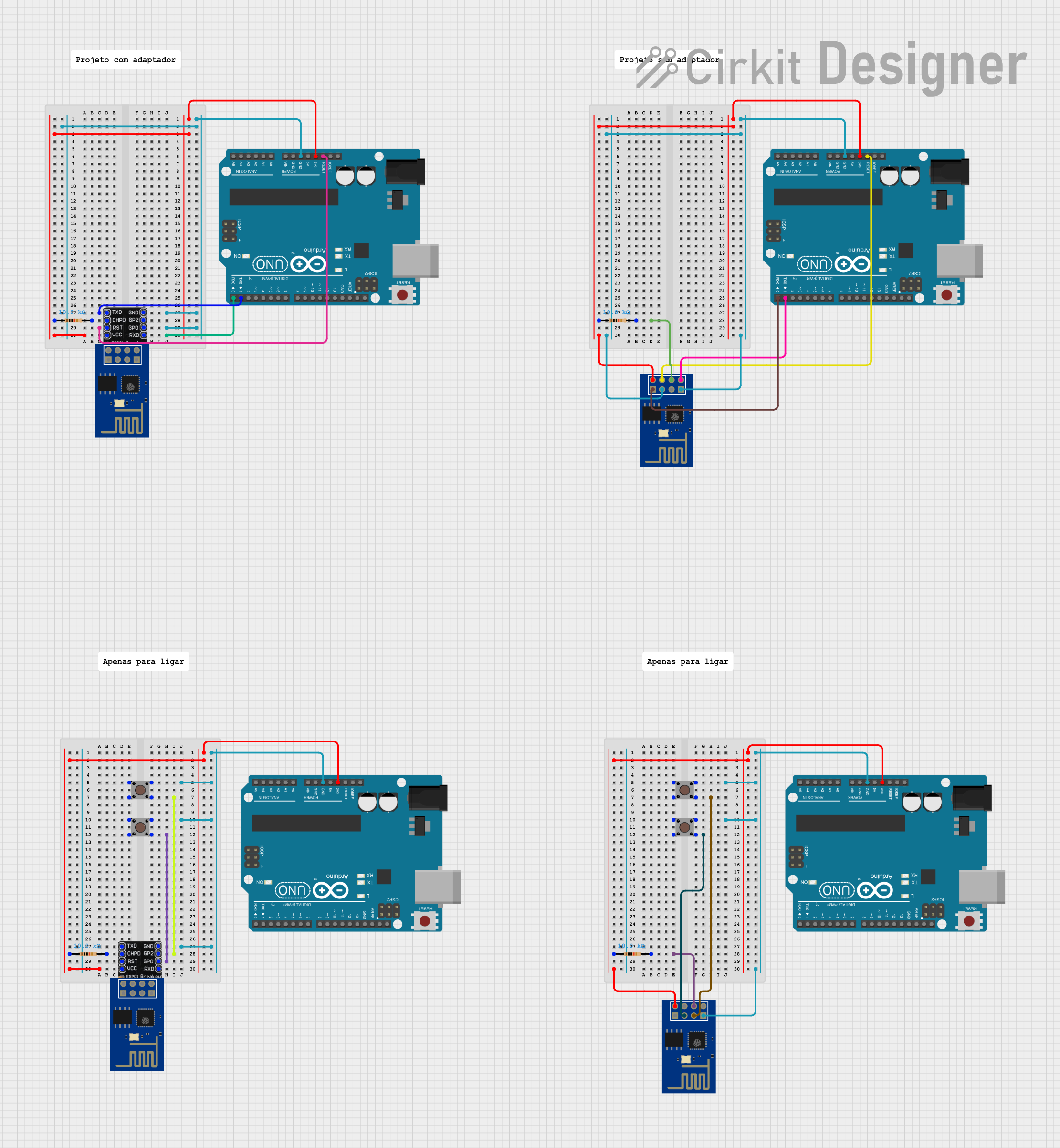
The circuit in question appears to be a prototype involving multiple microcontrollers (Arduino UNO boards) interfaced with ESP8266 ESP-01 WiFi modules through ESP-01 Breadboard Adapters. The circuit includes components for establishing WiFi connectivity and for user interaction through pushbuttons. Resistors are used for pull-up/pull-down configurations or to limit current. The exact functionality of the circuit is not specified, but it likely involves wireless communication and digital input handling.
Component List
Microcontrollers
- Arduino UNO: A microcontroller board based on the ATmega328P. It has 14 digital input/output pins, 6 analog inputs, a 16 MHz quartz crystal, a USB connection, a power jack, an ICSP header, and a reset button.
WiFi Modules
- ESP8266 ESP-01 WiFi Module: A self-contained SOC with integrated TCP/IP protocol stack that can give any microcontroller access to a WiFi network.
Adapters
- ESP-01 Breadboard Adapter: An adapter board for the ESP-01 module that makes it compatible with breadboard layouts, providing access to the module's pins.
Resistors
- 10k Ohm Resistor: A resistor with a resistance of 10,000 Ohms, commonly used for pull-up or pull-down resistors.
Pushbuttons
- Pushbutton: A simple switch mechanism for controlling some aspect of a machine or a process. Buttons are typically made out of hard material, usually plastic or metal.
Comments
- Comment: This component is likely a placeholder or annotation within the circuit design software and does not correspond to a physical component.
Wiring Details
Arduino UNO
- Digital Pins
- D0 connected to ESP-01 Breadboard Adapter RX (GPIO3)
- D1 connected to ESP-01 Breadboard Adapter TX (GPIO1)
- Power Pins
- 3.3V connected to ESP-01 Breadboard Adapter 3.3V through a 10k Ohm resistor
- GND connected to ESP-01 Breadboard Adapter GND
- Reset Pin
- Reset connected to ESP-01 Breadboard Adapter RESET
ESP-01 Breadboard Adapter
- TX (GPIO1) connected to Arduino UNO D1
- RX (GPIO3) connected to Arduino UNO D0
- CHPD connected to a 10k Ohm resistor
- RESET connected to Arduino UNO Reset
- 3.3V connected to Arduino UNO 3.3V through a 10k Ohm resistor
- GND connected to Arduino UNO GND
- GPIO0 connected to GND (possibly for programming mode)
- GPIO2 not explicitly connected in the provided net list
ESP8266 ESP-01 WiFi Module
- TXD connected to Arduino UNO D1
- RXD connected to Arduino UNO D0
- CH_PD connected to a 10k Ohm resistor
- RST connected to Arduino UNO Reset
- VCC connected to Arduino UNO 3.3V through a 10k Ohm resistor
- GND connected to Arduino UNO GND
- GPIO_0 connected to GND (possibly for programming mode)
- GPIO_2 not explicitly connected in the provided net list
Pushbutton
- Pin 1 (in) connected to GND
- Pin 3 (out) connected to ESP-01 Breadboard Adapter GPIO2 or GPIO0, or to ESP8266 ESP-01 WiFi Module GPIO_2 or GPIO_0
Resistor (10k Ohm)
- One end connected to ESP-01 Breadboard Adapter 3.3V or CH_PD
- The other end connected to Arduino UNO 3.3V or ESP8266 ESP-01 WiFi Module CH_PD or VCC
Documented Code
Arduino UNO (Multiple Instances)
Each Arduino UNO in the circuit has the same basic code structure with an empty setup() and loop() function. This code serves as a template and will need to be filled in with the specific logic required for the circuit's operation.
void setup() {
  // put your setup code here, to run once:

}

void loop() {
  // put your main code here, to run repeatedly:

}
The code is minimal and does not provide any specific functionality. Further development is required to implement the desired behavior of the microcontrollers in the circuit.