
ESP32-Controlled Ultrasonic Distance Measurement with Relay-Activated Pilot Lamps
View and Edit Project In Cirkit Designer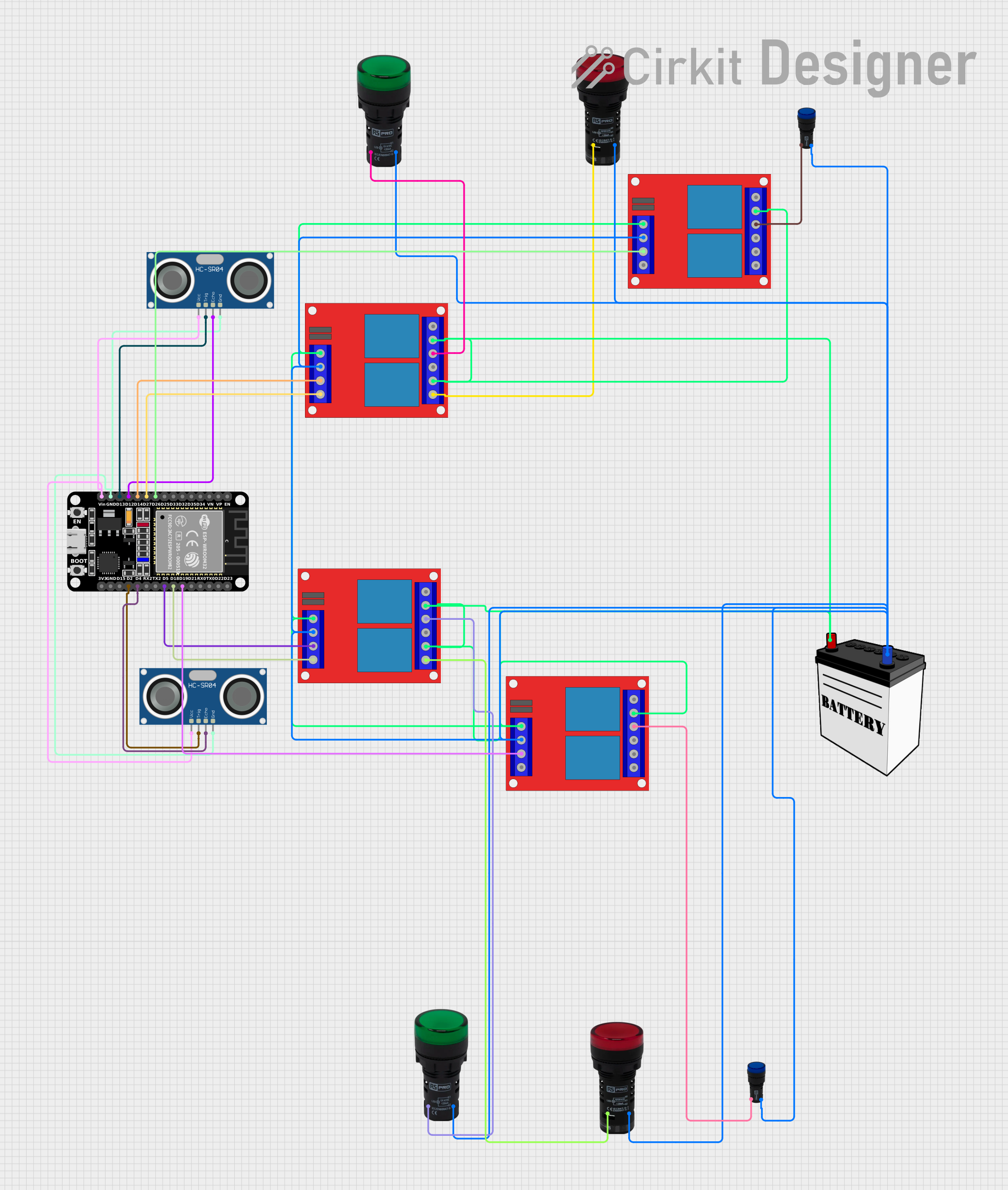
Circuit Documentation
Summary
The circuit in question is designed to interface an ESP32 microcontroller with various components including HC-SR04 Ultrasonic Sensors, Pilot Lamps (Green, Red, and Blue), and multiple 2 Channel 12V Relays. The ESP32 is responsible for controlling the relays based on the input from the ultrasonic sensors and indicating the system status through the pilot lamps. The circuit is powered by a 12V battery, which also supplies power to the relays.
Component List
ESP32 (30 pin)
- Description: A microcontroller with WiFi and Bluetooth capabilities, featuring a wide range of GPIO pins.
- Pins: EN, VP, VN, D34, D35, D32, D33, D25, D26, D27, D14, D12, D13, GND, Vin, D23, D22, TX0, RX0, D21, D19, D18, D5, TX2, RX2, D4, D2, D15, 3V3
Pilot Lamp Green
- Description: An indicator lamp that lights up green.
- Pins: X1, X2
Pilot Lamp Red
- Description: An indicator lamp that lights up red.
- Pins: X1, X2
HC-SR04 Ultrasonic Sensor
- Description: A sensor used to measure distance via ultrasonic waves.
- Pins: VCC, TRIG, ECHO, GND
2 Channel 12V Relay
- Description: A relay module with two channels, capable of controlling high power devices.
- Pins: 12v +, 12v -, Trigger 1, Trigger 2, NC1, COM1, NO1, NC2, COM2, NO2
Pilot Lamp Blue
- Description: An indicator lamp that lights up blue.
- Pins: x1, x2
12V Battery
- Description: A power source for the circuit.
- Pins: VCC, GND
Wiring Details
ESP32 (30 pin)
- D26 connected to Relay (Trigger 1)
- D27 connected to Relay (Trigger 2)
- D14 connected to Relay (Trigger 1)
- D12 connected to Ultrasonic Sensor (ECHO)
- D13 connected to Ultrasonic Sensor (TRIG)
- GND connected to Ultrasonic Sensor (GND) and Relays (12v -)
- Vin connected to Ultrasonic Sensor (VCC)
- D19 connected to Relay (Trigger 1)
- D18 connected to Relay (Trigger 2)
- D5 connected to Relay (Trigger 1)
- D4 connected to Ultrasonic Sensor (ECHO)
- D2 connected to Ultrasonic Sensor (TRIG)
Pilot Lamp Green
- X1 connected to Relay (NO1)
- X2 connected to Battery (GND)
Pilot Lamp Red
- X1 connected to Relay (NO2)
- X2 connected to Battery (GND)
HC-SR04 Ultrasonic Sensor
- VCC connected to ESP32 (Vin)
- TRIG connected to ESP32 (D13 or D2)
- ECHO connected to ESP32 (D12 or D4)
- GND connected to ESP32 (GND)
2 Channel 12V Relay
- 12v + connected to Battery (VCC)
- 12v - connected to Battery (GND)
- Trigger 1 connected to ESP32 (D26, D14, or D19)
- Trigger 2 connected to ESP32 (D27, D18)
- NO1 connected to Pilot Lamp Green (X1)
- NO2 connected to Pilot Lamp Red (X1)
- COM1 and COM2 connected to Battery (VCC)
Pilot Lamp Blue
- x1 connected to Relay (NO1)
- x2 connected to Battery (GND)
12V Battery
- VCC connected to Relays (12v +)
- GND connected to Relays (12v -), Pilot Lamps (X2)
Documented Code
Code for ESP32 (30 pin)
const int trigPin = 12;
const int echoPin = 13;
const int relayGreen1 = 14;

// Define sound speed in cm/uS
#define SOUND_SPEED 0.034
#define CM_TO_INCH 0.393701

long duration;
int distanceCm;
int distanceInch;

void setup() {
  Serial.begin(115200);
  pinMode(trigPin, OUTPUT); // Sets the trigPin as an Output
  pinMode(echoPin, INPUT);  // Sets the echoPin as an Input

  pinMode(relayGreen1, OUTPUT);
}

void loop() {
  // Clears the trigPin
  digitalWrite(trigPin, LOW);
  delayMicroseconds(2);
  // Sets the trigPin on HIGH state for 10 micro seconds
  digitalWrite(trigPin, HIGH);
  delayMicroseconds(10);
  digitalWrite(trigPin, LOW);

  // Reads the echoPin, returns the sound wave travel time in microseconds
  duration = pulseIn(echoPin, HIGH);

  // Calculate the distance
  distanceCm = duration * SOUND_SPEED / 2;

  // Convert to inches
  distanceInch = distanceCm * CM_TO_INCH;

  // Prints the distance in the Serial Monitor
  Serial.print("Distance (cm): ");
  Serial.println(distanceCm);
  Serial.print("Distance (inch): ");
  Serial.println(distanceInch);

  // Normally Open configuration, send LOW signal to let current flow
  digitalWrite(relayGreen1, LOW);
  Serial.println("Current Flowing");
  delay(5000);

  // Normally Open configuration, send HIGH signal to stop current flow
  digitalWrite(relayGreen1, HIGH);
  Serial.println("Current not Flowing");
  delay(5000);
}
(Note: The code provided is associated with the ESP32 microcontroller and is intended to control a relay based on the distance measured by the ultrasonic sensor. The code includes setup and loop functions that initialize the pins and perform the distance measurement and relay control in a continuous loop. The relay is activated for 5 seconds and then deactivated for 5 seconds in a repeating cycle.)