
Arduino UNO R4 WiFi-Controlled Object Detection System with I2C LCD Feedback and Relay-Servo Activation
View and Edit Project In Cirkit Designer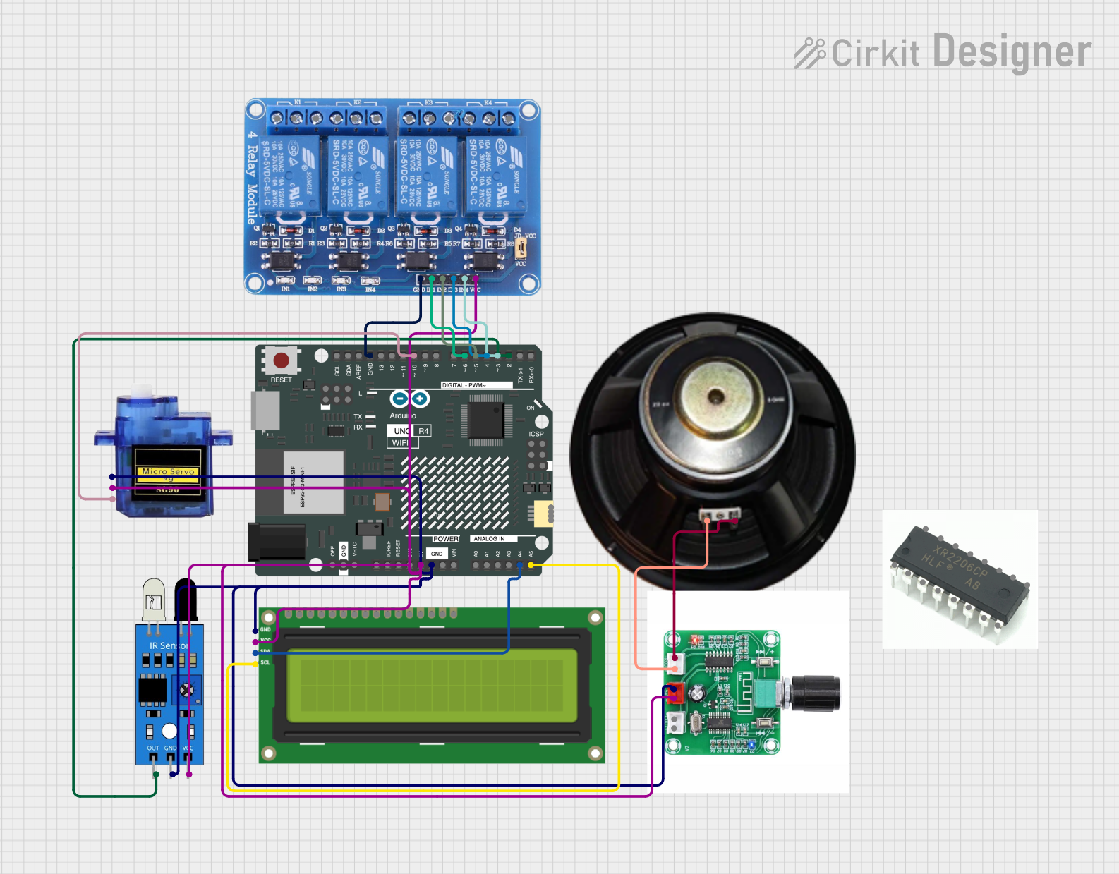
Circuit Documentation
Summary
This circuit is designed to interface an Arduino UNO R4 WiFi with multiple peripherals including an I2C LCD 16x2 Screen, a 4-channel 5V relay module, an IR sensor, a micro servo 9G, a speaker, and a PAM8403 5W Bluetooth 5.0 Digital Stereo Power Audio Amplifier. The Arduino board serves as the central processing unit, controlling the relay module and servo based on input from the IR sensor. The LCD screen displays system status and frequency information, while the speaker generates sound at a specified frequency driven by the Arduino. The PAM8403 amplifier is connected to the speaker to amplify the audio signal.
Component List
Arduino UNO R4 WiFi
- Microcontroller board with WiFi capability.
- Pins: OFF, GND, VRTC, IIC0_SCL, IIC0_SDA, 3V3, GPIO 41, GPIO 0, GPIO 42, GPIO 43, GPIO 44, BOOT, IOREF, RESET, 5V, VIN, A0, A1, A2, A3, A4, A5, RSPCKA, CIPO, COPI, D0/RX, D1/TX, D2, D3, D4, D5, D6, D7, D8, D9, D10, D11, D12, D13, AREF, SDA, SCL.
I2C LCD 16x2 Screen
- A liquid crystal display that uses the I2C communication protocol.
- Pins: SCL, SDA, VCC (5V), GND, VDD, VO, RS, RW, E, D0, D1, D2, D3, D4, D5, D6, D7, BLA, BLK.
Relay 4 Channel 5v
- A module with 4 relays that can be individually controlled to switch external circuits.
- Pins: GND, IN1, IN2, IN3, IN4, VCC, COM1, COM2, COM3, COM4, NO1, NO2, NO3, NO4, NC1, NC2, NC3, NC4.
IR Sensor
- A sensor that detects infrared light, often used for proximity or motion detection.
- Pins: out, gnd, vcc.
Micro Servo 9G
- A small servo motor capable of precise position control.
- Pins: GND, +5V, PWM.
Speaker
- An electroacoustic transducer that converts electrical audio signal into sound.
- Pins: +, -.
PAM8403 5W Bluetooth 5.0 Digital Stereo Power Audio Amplifier
- A digital amplifier for driving speakers with Bluetooth 5.0 support.
- Pins: -, +.
Wiring Details
Arduino UNO R4 WiFi
- 5V: Connected to VCC of I2C LCD, Relay Module, IR Sensor, Micro Servo, and PAM8403 Amplifier.
- GND: Connected to GND of I2C LCD, Relay Module, IR Sensor, Micro Servo, and PAM8403 Amplifier.
- A4 (SDA): Connected to SDA of I2C LCD.
- A5 (SCL): Connected to SCL of I2C LCD.
- D2: Connected to the output of the IR Sensor.
- D3: Connected to IN4 of Relay Module.
- D4: Connected to IN3 of Relay Module.
- D5: Connected to IN2 of Relay Module.
- D6: Connected to IN1 of Relay Module.
- D10: Connected to PWM of Micro Servo.
I2C LCD 16x2 Screen
- SCL: Connected to A5 (SCL) of Arduino UNO R4 WiFi.
- SDA: Connected to A4 (SDA) of Arduino UNO R4 WiFi.
- VCC (5V): Connected to 5V of Arduino UNO R4 WiFi.
- GND: Connected to GND of Arduino UNO R4 WiFi.
Relay 4 Channel 5v
- VCC: Connected to 5V of Arduino UNO R4 WiFi.
- GND: Connected to GND of Arduino UNO R4 WiFi.
- IN1: Connected to D6 of Arduino UNO R4 WiFi.
- IN2: Connected to D5 of Arduino UNO R4 WiFi.
- IN3: Connected to D4 of Arduino UNO R4 WiFi.
- IN4: Connected to D3 of Arduino UNO R4 WiFi.
IR Sensor
- vcc: Connected to 5V of Arduino UNO R4 WiFi.
- gnd: Connected to GND of Arduino UNO R4 WiFi.
- out: Connected to D2 of Arduino UNO R4 WiFi.
Micro Servo 9G
- +5V: Connected to 5V of Arduino UNO R4 WiFi.
- GND: Connected to GND of Arduino UNO R4 WiFi.
- PWM: Connected to D10 of Arduino UNO R4 WiFi.
Speaker
- +: Connected to + of PAM8403 Amplifier.
- -: Connected to - of PAM8403 Amplifier.
PAM8403 5W Bluetooth 5.0 Digital Stereo Power Audio Amplifier
- +: Connected to 5V of Arduino UNO R4 WiFi and + of Speaker.
- -: Connected to GND of Arduino UNO R4 WiFi and - of Speaker.
Documented Code
/*
 * This Arduino sketch interfaces with an I2C LCD, IR sensor, relay module,
 * micro servo, and a speaker. The IR sensor detects objects and triggers
 * relays and servo movements. The LCD displays system status and frequency
 * information. The speaker generates a soundwave at a specified frequency.
 */

#include <Wire.h>
#include <hd44780.h>           // main hd44780 header
#include <hd44780ioClass/hd44780_I2Cexp.h> // i2c expander i/o class header
#include <Servo.h>

// I2C LCD setup
hd44780_I2Cexp lcd; // declare lcd object: auto locate & auto config expander chip

// Pin definitions
#define IR_SENSOR_PIN 2
#define RELAY_PIN_1 6
#define RELAY_PIN_2 5
#define RELAY_PIN_3 4
#define RELAY_PIN_4 3
#define SERVO_PIN 10
#define SPEAKER_PIN 8

// Servo setup
Servo myServo;

void setup() {
  // Initialize serial communication
  Serial.begin(9600);

  // Initialize LCD
  lcd.init();
  lcd.backlight();
  lcd.setCursor(0, 0);
  lcd.print("System Initializing");

  // Initialize pins
  pinMode(IR_SENSOR_PIN, INPUT);
  pinMode(RELAY_PIN_1, OUTPUT);
  pinMode(RELAY_PIN_2, OUTPUT);
  pinMode(RELAY_PIN_3, OUTPUT);
  pinMode(RELAY_PIN_4, OUTPUT);
  myServo.attach(SERVO_PIN);

  // Initial states
  digitalWrite(RELAY_PIN_1, LOW);
  digitalWrite(RELAY_PIN_2, LOW);
  digitalWrite(RELAY_PIN_3, LOW);
  digitalWrite(RELAY_PIN_4, LOW);
  myServo.write(0);

  lcd.setCursor(0, 1);
  lcd.print("Ready");
}

void loop() {
  // Read IR sensor
  int irValue = digitalRead(IR_SENSOR_PIN);

  if (irValue == HIGH) {
    // Object detected
    lcd.setCursor(0, 1);
    lcd.print("Object Detected ");
    digitalWrite(RELAY_PIN_1, HIGH);
    digitalWrite(RELAY_PIN_2, HIGH);
    digitalWrite(RELAY_PIN_3, HIGH);
    digitalWrite(RELAY_PIN_4, HIGH);
    myServo.write(90); // Move servo to 90 degrees
    delay(1000); // Wait for the servo to move
  } else {
    // No object detected
    lcd.setCursor(0, 1);
    lcd.print("No Object       ");
    digitalWrite(RELAY_PIN_1, LOW);
    digitalWrite(RELAY_PIN_2, LOW);
    digitalWrite(RELAY_PIN_3, LOW);
    digitalWrite(RELAY_PIN_4, LOW);
    myServo.write(0); // Move servo back to 0 degrees
    delay(1000); // Wait for the servo to move
  }

  // Generate soundwave frequency
  int frequency = 1000; // 1000 Hz frequency
  tone(SPEAKER_PIN, frequency); // Pin 8, 1000 Hz frequency
  delay(1000); // 1 second delay
  noTone(SPEAKER_PIN); // Stop tone
  delay(1000); // 1 second delay

  // Display frequency on LCD
  lcd.setCursor(0, 1);
  lcd.print("Freq: ");
  lcd.print(frequency);
  lcd.print(" Hz ");
}
This code is responsible for controlling the various components of the circuit. It initializes the LCD and sets up the pins for the IR sensor, relay module, servo, and speaker. The main loop reads the IR sensor and activates the relays and servo accordingly. It also generates a tone on the speaker and displays the frequency on the LCD.