
Arduino UNO Controlled Multiplexer-Based LED Array with Battery Power
View and Edit Project In Cirkit Designer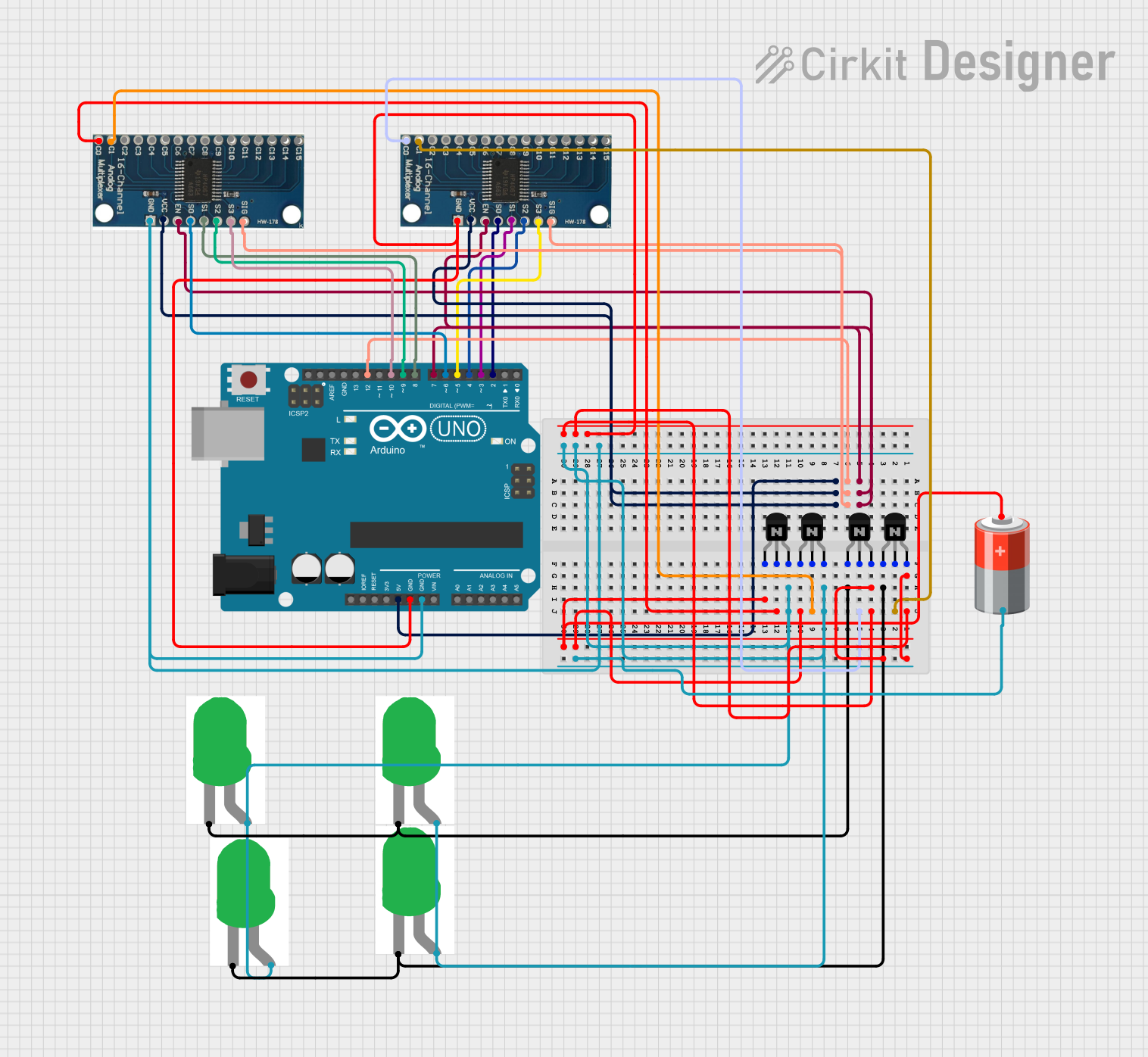
Circuit Documentation
Summary
This circuit involves an Arduino UNO microcontroller, two 16-channel analog multiplexers, four NPN transistors, four green LEDs, and a 5V battery. The Arduino UNO controls the multiplexers and transistors to manage the LEDs. The multiplexers are used to select which transistor base to activate, thereby controlling the LEDs.
Component List
Arduino UNO
- Description: Microcontroller board based on the ATmega328P.
- Pins: UNUSED, IOREF, Reset, 3.3V, 5V, GND, Vin, A0, A1, A2, A3, A4, A5, SCL, SDA, AREF, D13, D12, D11, D10, D9, D8, D7, D6, D5, D4, D3, D2, D1, D0
16 Channel Analog Multiplexer Bob (x2)
- Description: Analog multiplexer with 16 channels.
- Pins: GND, VCC, EN, S0, S1, S2, S3, SIG, C0, C1, C2, C3, C4, C5, C6, C7, C8, C9, C10, C11, C12, C13, C14, C15
NPN Transistor (CBE) (x4)
- Description: NPN transistor with collector, base, and emitter pins.
- Pins: collector, base, emitter
5V Battery
- Description: Power source providing 5V.
- Pins: +, -
LED: Two Pin (green) (x4)
- Description: Green LED with cathode and anode pins.
- Pins: cathode, anode
Wiring Details
Arduino UNO
- GND: Connected to the GND pins of both multiplexers, the emitters of two transistors, and the negative terminal of the 5V battery.
- 5V: Connected to the VCC pins of both multiplexers.
- D2: Connected to the S0 pin of the second multiplexer.
- D3: Connected to the S1 pin of the second multiplexer.
- D4: Connected to the S2 pin of the second multiplexer.
- D5: Connected to the S3 pin of the second multiplexer.
- D6: Connected to the S0 pin of the first multiplexer.
- D7: Connected to the EN pins of both multiplexers.
- D8: Connected to the S1 pin of the first multiplexer.
- D9: Connected to the S2 pin of the first multiplexer.
- D10: Connected to the S3 pin of the first multiplexer.
- D12: Connected to the SIG pins of both multiplexers.
16 Channel Analog Multiplexer Bob (First)
- GND: Connected to the GND pin of the Arduino UNO.
- VCC: Connected to the 5V pin of the Arduino UNO.
- EN: Connected to the D7 pin of the Arduino UNO.
- S0: Connected to the D6 pin of the Arduino UNO.
- S1: Connected to the D8 pin of the Arduino UNO.
- S2: Connected to the D9 pin of the Arduino UNO.
- S3: Connected to the D10 pin of the Arduino UNO.
- SIG: Connected to the D12 pin of the Arduino UNO.
- C0: Connected to the base of one NPN transistor.
- C1: Connected to the base of another NPN transistor.
16 Channel Analog Multiplexer Bob (Second)
- GND: Connected to the GND pin of the Arduino UNO.
- VCC: Connected to the 5V pin of the Arduino UNO.
- EN: Connected to the D7 pin of the Arduino UNO.
- S0: Connected to the D2 pin of the Arduino UNO.
- S1: Connected to the D3 pin of the Arduino UNO.
- S2: Connected to the D4 pin of the Arduino UNO.
- S3: Connected to the D5 pin of the Arduino UNO.
- SIG: Connected to the D12 pin of the Arduino UNO.
- C0: Connected to the base of one NPN transistor.
- C1: Connected to the base of another NPN transistor.
NPN Transistor (x4)
- Collector: Connected to the positive terminal of the 5V battery.
- Base: Connected to the respective multiplexer channel (C0 or C1).
- Emitter: Connected to the anode of the respective LED.
5V Battery
- +: Connected to the collectors of all NPN transistors.
- -: Connected to the GND pin of the Arduino UNO.
LED: Two Pin (green) (x4)
- Cathode: Connected to the collector of the respective NPN transistor.
- Anode: Connected to the emitter of the respective NPN transistor.
Code Documentation
Arduino UNO Code
void setup() {
  pinMode(2, OUTPUT);
  pinMode(3, OUTPUT);
  pinMode(4, OUTPUT);
  pinMode(5, OUTPUT);
  pinMode(6, OUTPUT);
  pinMode(7, OUTPUT);
  pinMode(8, OUTPUT);
  pinMode(9, OUTPUT);
  pinMode(10, OUTPUT);
  pinMode(11, OUTPUT);
  pinMode(12, OUTPUT);
  pinMode(13, OUTPUT);
  digitalWrite(12, 1);
  digitalWrite(7, 0);
}

void loop() {
  digitalWrite(2, 0);
  digitalWrite(3, 0);
  digitalWrite(4, 0);
  digitalWrite(5, 0);
  digitalWrite(6, 0);
  digitalWrite(8, 0);
  digitalWrite(9, 0);
  digitalWrite(10, 0);
}
This code initializes the digital pins of the Arduino UNO as outputs and sets the initial states of pins 12 and 7. The loop function sets the states of pins 2 through 10 to low.