
Solar-Powered ESP32 IoT Device with Battery Backup and Power Management
View and Edit Project In Cirkit Designer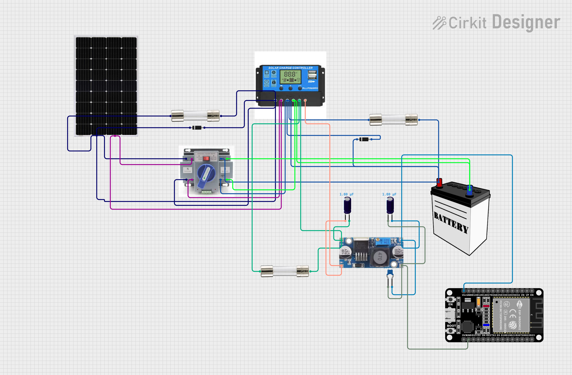
Circuit Documentation
Summary of the Circuit
This circuit is designed to be powered by a solar panel and a 12V battery, which are managed by a charge controller. The charge controller ensures the battery is charged from the solar panel and also provides a regulated power supply to the load. A step-down buck converter is used to step down the voltage to a level suitable for the ESP32 microcontroller. Protection is provided by fuses and diodes to prevent overcurrent and reverse current flow, respectively. Capacitors are used for voltage smoothing and to reduce power supply noise.
Component List
ESP32 (30 pin)
- Description: A microcontroller with Wi-Fi and Bluetooth capabilities.
- Pins: EN, VP, VN, D34, D35, D32, D33, D25, D26, D27, D14, D12, D13, GND, Vin, D23, D22, TX0, RX0, D21, D19, D18, D5, TX2, RX2, D4, D2, D15, 3V3
Solar Panel
- Description: A photovoltaic panel for converting solar energy into electrical energy.
- Pins: +, -
12V Battery
- Description: A rechargeable battery providing a 12V supply.
- Pins: VCC, GND
ATS (Automatic Transfer Switch)
- Description: A switch that automatically transfers power between the solar panel and the battery.
- Pins: +, -
Charge Controller
- Description: Manages the power coming from the solar panel to charge the battery and provides power to the load.
- Pins: Solar Positive, Solar Negative, Battery Positive, Battery Negative, Load Positive, Load Negative
Fuse
- Description: A safety device that protects the circuit from overcurrent by breaking the circuit if current exceeds a certain threshold.
- Pins: Terminal 1, Terminal 2
Diode
- Description: A semiconductor device that allows current to flow in one direction only, used to prevent reverse current flow.
- Pins: cathode, anode
Electrolytic Capacitor
- Description: A capacitor used for filtering and smoothing the voltage supply.
- Pins: -, +
- Properties: Capacitance: 1 µF (microfarads)
Ceramic Capacitor
- Description: A small-value capacitor used for decoupling and noise reduction in the circuit.
- Pins: pin0, pin1
- Properties: Capacitance: 0.1 µF (microfarads)
Step-down Buck Converter
- Description: A DC-DC converter that steps down voltage from a higher level to a lower level.
- Pins: IN +, IN - GND, OUT +, OUT - GND
Wiring Details
ESP32 (30 pin)
- Vin connected to the output of the step-down buck converter.
- GND connected to the ground of the step-down buck converter.
Solar Panel
-
- connected to the solar positive of the charge controller through a diode and ATS.
-
- connected to the solar negative of the charge controller and ATS.
12V Battery
- VCC connected to the battery positive of the charge controller through a diode and ATS.
- GND connected to the battery negative of the charge controller and ATS.
ATS (Automatic Transfer Switch)
-
- connected to the solar panel, charge controller, and fuses.
-
- connected to the solar panel, charge controller, and 12V battery.
Charge Controller
- Solar Positive connected to the solar panel through a diode.
- Solar Negative connected to the solar panel.
- Battery Positive connected to the 12V battery through a diode.
- Battery Negative connected to the 12V battery.
- Load Positive connected to the input of the step-down buck converter through a fuse.
- Load Negative connected to the input of the step-down buck converter.
Fuse
- Terminal 1 connected to the ATS and charge controller.
- Terminal 2 connected to the solar panel, charge controller, and step-down buck converter.
Diode
- cathode connected to the charge controller.
- anode connected to the solar panel and 12V battery.
Electrolytic Capacitor
-
- connected to the output of the step-down buck converter and the input of the charge controller.
-
- connected to the ground of the step-down buck converter and the input of the charge controller.
Ceramic Capacitor
- pin1 connected to the output of the step-down buck converter.
- pin0 connected to the ground of the step-down buck converter.
Step-down Buck Converter
- IN + connected to the load positive of the charge controller through a fuse.
- IN - GND connected to the load negative of the charge controller.
- OUT + connected to Vin of the ESP32 and a ceramic capacitor.
- OUT - GND connected to GND of the ESP32 and a ceramic capacitor.
Documented Code
Microcontroller Code (ESP32)
void setup() {
  // put your setup code here, to run once:

}

void loop() {
  // put your main code here, to run repeatedly:

}
Filename: sketch.ino
(Note: The provided code is a template and does not contain any functional code specific to the operation of the circuit. Additional code is required to control and monitor the components within the circuit.)