Arduino Mega 2560-Based Multi-Functional Vehicle with GPS and GSM
Circuit Documentation
Summary
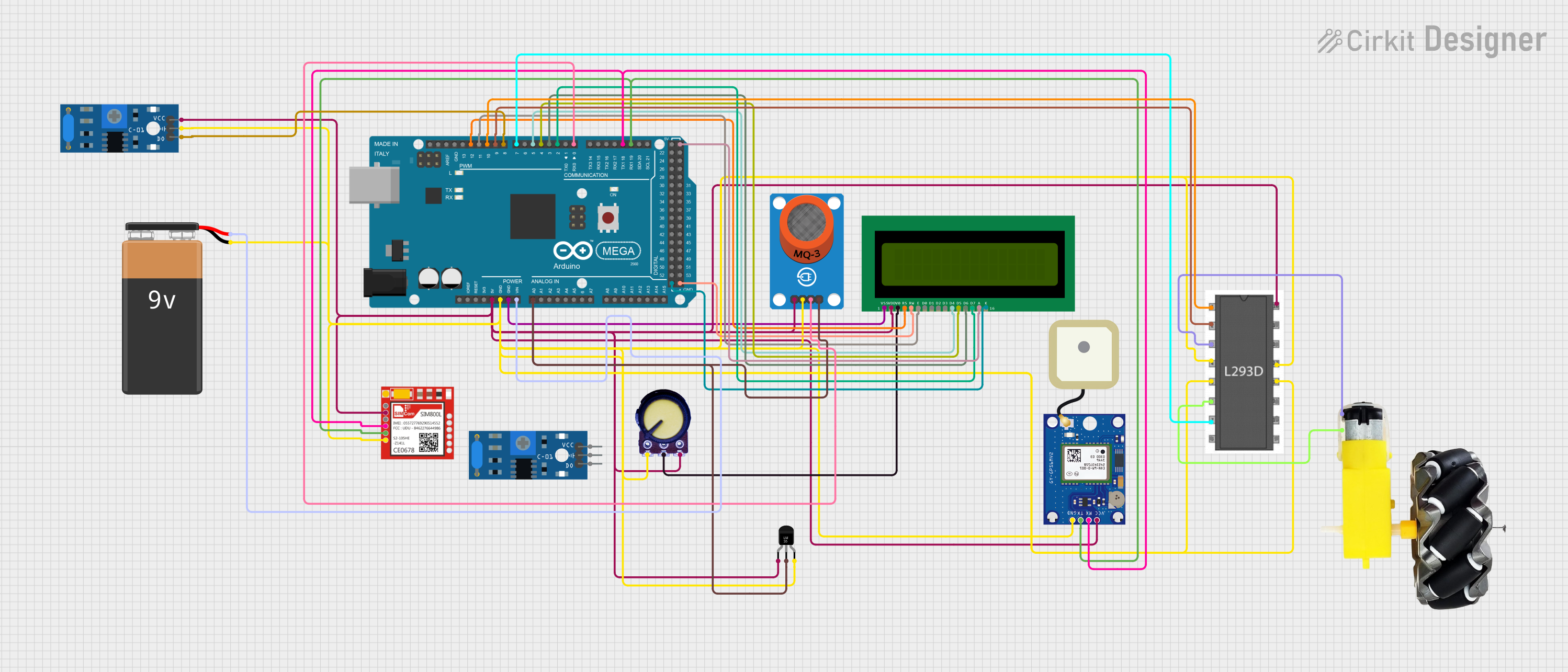
This document provides a detailed overview of a circuit designed to interface various sensors and modules with an Arduino Mega 2560 microcontroller. The circuit includes a range of components such as sensors, a motor driver, a display, communication modules, and a power source. The purpose of the circuit is not explicitly stated, but it appears to be a sensor-rich platform possibly for data acquisition, monitoring, or a mobile platform given the inclusion of a motor and wheels.
Component List
Arduino Mega 2560
- Microcontroller board based on the ATmega2560
- Offers a large number of IO pins, including digital, analog, PWM, and communication pins
MQ-3 Breakout
- Alcohol sensor module
- Provides both analog and digital outputs
16X2 LCD
- Alphanumeric liquid crystal display
- Capable of displaying 16 characters in 2 rows
Sim800l
- GSM/GPRS communication module
- Allows for cellular network connectivity for calls, SMS, and data
GPS NEO-6M V2
- GPS module for satellite-based positioning
- Provides serial communication via TX/RX pins
L293D
- Motor driver IC
- Capable of driving two DC motors with direction and speed control
Temperature Sensor (LM35)
- Analog temperature sensor
- Provides a linearly proportional voltage output to the measured temperature
Potentiometer
- Variable resistor
- Typically used for adjusting a parameter or as a voltage divider
Motor and Wheels
- DC motor with attached wheels
- Used for mobility in robotics applications
9V Battery
- Power source
- Provides voltage supply to the circuit
SW-420 Vibration Sensor
- Vibration detection module
- Offers a digital output signal upon detecting vibration
Wiring Details
Arduino Mega 2560
5VandGNDpins are used to distribute power to other components in the circuit.VINis connected to the positive terminal of the 9V battery.- Analog and digital IO pins are connected to various sensors and modules for interfacing and control.
MQ-3 Breakout
VCCconnected to 5V power railGNDconnected to ground railAO(Analog Output) connected toA0on Arduino Mega 2560DO(Digital Output) connected toD0 RX0on Arduino Mega 2560
16X2 LCD
VDDconnected to 5V power railVSSandRWconnected to ground railV0connected to the output of the potentiometer for contrast adjustmentRS,E,D4,D5,D6, andD7connected to digital pinsD12 PWM,D11 PWM,D5 PWM,D4 PWM,D3 PWM, andD2 PWMon Arduino Mega 2560 respectivelyA(Anode) connected to 5V power rail for backlightK(Cathode) connected to ground rail for backlight
Sim800l
VCCconnected to 5V power railGNDconnected to ground railTXDconnected toD19/RX1on Arduino Mega 2560RXDconnected toD18/TX1on Arduino Mega 2560
GPS NEO-6M V2
VCCconnected to 5V power railGNDconnected to ground railTXconnected toD19/RX1on Arduino Mega 2560RXconnected toD18/TX1on Arduino Mega 2560
L293D
Vcc1connected to 5V power railGNDpins connected to ground railEnable 1,2connected toD10 PWMon Arduino Mega 2560Input 1connected toD9 PWMon Arduino Mega 2560Input 2connected toD7 PWMon Arduino Mega 2560Output 1andOutput 2connected to the motor and wheels
Temperature Sensor (LM35)
+Vsconnected to 5V power railGNDconnected to ground railVoutconnected toA0on Arduino Mega 2560
Potentiometer
VCCconnected to 5V power railGNDconnected to ground railOutputconnected toV0on 16X2 LCD for contrast control
Motor and Wheels
vccconnected toOutput 1on L293DGNDconnected toOutput 2on L293D
SW-420 Vibration Sensor
vccconnected to 5V power railGroundconnected to ground railDigital outputconnected toD8 PWMon Arduino Mega 2560
9V Battery
+connected toVINon Arduino Mega 2560-connected to ground rail
Documented Code
Arduino Mega 2560 - sketch.ino
void setup() {
  // put your setup code here, to run once:

}

void loop() {
  // put your main code here, to run repeatedly:

}
Arduino Mega 2560 - documentation.txt
The code for the Arduino Mega 2560 is currently a template with empty setup() and loop() functions. The setup() function is intended for initialization code that runs once at the start, such as pin mode declarations. The loop() function is for code that runs continuously, handling the main functionality of the microcontroller.
Further implementation details would be required to provide a complete documentation of the code, including the specific logic for sensor readings, motor control, display updates, and communication handling.