
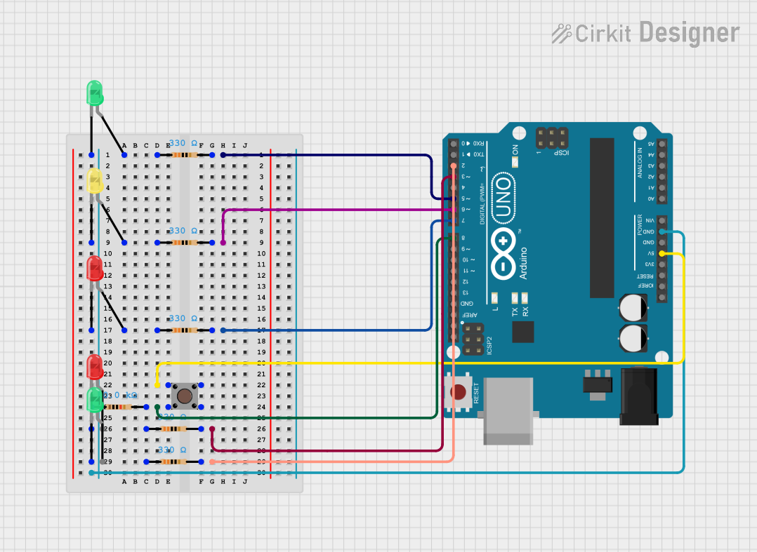
Circuit Documentation
Summary
This circuit is designed to control a traffic light system with pedestrian crossing functionality using an Arduino UNO microcontroller. The system includes three LEDs for car traffic (red, yellow, green) and two LEDs for pedestrian traffic (red, green). A pushbutton allows pedestrians to request to cross. The car traffic light follows a sequence with defined delays, and when the button is pressed, the pedestrian light turns green, allowing pedestrians to cross.
Component List
Arduino UNO
- Description: Microcontroller board based on the ATmega328P.
- Pins: UNUSED, IOREF, Reset, 3.3V, 5V, GND, Vin, A0, A1, A2, A3, A4, A5, SCL, SDA, AREF, D13, D12, D11, D10, D9, D8, D7, D6, D5, D4, D3, D2, D1, D0
LED: Two Pin (red)
- Description: Red LED.
- Pins: cathode, anode
LED: Two Pin (yellow)
- Description: Yellow LED.
- Pins: cathode, anode
LED: Two Pin (green)
- Description: Green LED.
- Pins: cathode, anode
Resistor (330 Ohms)
- Description: Resistor with 330 Ohms resistance.
- Pins: pin1, pin2
Resistor (10k Ohms)
- Description: Resistor with 10k Ohms resistance.
- Pins: pin1, pin2
Pushbutton
- Description: Pushbutton switch.
- Pins: Pin 3 (out), Pin 4 (out), Pin 1 (in), Pin 2 (in)
Wiring Details
Arduino UNO
- D5 connected to Resistor (330 Ohms) pin2
- D6 connected to Resistor (330 Ohms) pin2
- D7 connected to Resistor (330 Ohms) pin2
- 5V connected to Pushbutton Pin 2 (in)
- D8 connected to Pushbutton Pin 4 (out) and Resistor (10k Ohms) pin2
- D3 connected to Resistor (330 Ohms) pin2
- D2 connected to Resistor (330 Ohms) pin2
- GND connected to:
- LED: Two Pin (red) cathode
- LED: Two Pin (yellow) cathode
- LED: Two Pin (green) cathode
- Resistor (10k Ohms) pin1
- LED: Two Pin (red) cathode
- LED: Two Pin (green) cathode
LED: Two Pin (red)
- anode connected to Resistor (330 Ohms) pin1
LED: Two Pin (yellow)
- anode connected to Resistor (330 Ohms) pin1
LED: Two Pin (green)
- anode connected to Resistor (330 Ohms) pin1
Resistor (330 Ohms)
- pin2 connected to Arduino UNO D5
- pin2 connected to Arduino UNO D6
- pin2 connected to Arduino UNO D7
- pin2 connected to Arduino UNO D3
- pin2 connected to Arduino UNO D2
Resistor (10k Ohms)
- pin2 connected to Arduino UNO D8
- pin1 connected to Arduino UNO GND
Pushbutton
- Pin 2 (in) connected to Arduino UNO 5V
- Pin 4 (out) connected to Resistor (10k Ohms) pin2 and Arduino UNO D8
Code Documentation
/*
 * This Arduino sketch controls a traffic light system with pedestrian
 * crossing functionality. The system includes three LEDs for car traffic
 * (red, yellow, green) connected to pins 7, 6, and 5 respectively, and
 * two LEDs for pedestrian traffic (red, green) connected to pins 3 and 2
 * respectively. A button connected to pin 8 allows pedestrians to request
 * to cross. The car traffic light follows a sequence with delays defined
 * by DELAY0, DELAY1, DELAY2, and DELAY3. When the button is pressed, the
 * pedestrian light turns green, allowing pedestrians to cross.
 */

#define DELAY0 10000
#define DELAY1 1000
#define DELAY2 2000
#define DELAY3 3000

int ledPinRedCar = 7;
int ledPinOrangeCar = 6;
int ledPinGreenCar = 5;
int ledPinRedWalk = 3;
int ledPinGreenWalk = 2;
int buttonPinLight = 8;
int buttonLightValue = LOW;

void setup() {
  pinMode(ledPinRedCar, OUTPUT);
  pinMode(ledPinOrangeCar, OUTPUT);
  pinMode(ledPinGreenCar, OUTPUT);
  pinMode(ledPinRedWalk, OUTPUT);
  pinMode(ledPinGreenWalk, OUTPUT);
  pinMode(buttonPinLight, INPUT);
}

void loop() {
  buttonLightValue = digitalRead(buttonPinLight);
  if (buttonLightValue == HIGH) {
    digitalWrite(ledPinRedCar, HIGH);
    digitalWrite(ledPinGreenCar, LOW);
    digitalWrite(ledPinOrangeCar, LOW);
    digitalWrite(ledPinRedWalk, LOW);
    digitalWrite(ledPinGreenWalk, HIGH);
    delay(DELAY3);
    digitalWrite(ledPinGreenWalk, LOW);
    digitalWrite(ledPinRedWalk, HIGH);
  } else {
    digitalWrite(ledPinGreenCar, HIGH);
    digitalWrite(ledPinRedCar, LOW);
    digitalWrite(ledPinOrangeCar, LOW);
    delay(DELAY0);
    digitalWrite(ledPinGreenCar, LOW);
    digitalWrite(ledPinOrangeCar, HIGH);
    delay(DELAY1);
    digitalWrite(ledPinOrangeCar, LOW);
    digitalWrite(ledPinRedCar, HIGH);
    delay(DELAY2);
  }
}
This code controls the traffic light system, switching between car and pedestrian lights based on the state of the pushbutton. The car lights follow a sequence with defined delays, and the pedestrian light turns green when the button is pressed, allowing pedestrians to cross.