Cirkit Designer
Your all-in-one circuit design IDE
Home /
Project Documentation
ESP32-Based RFID Access Control System with LCD Display and Buzzer
Circuit Documentation
Summary
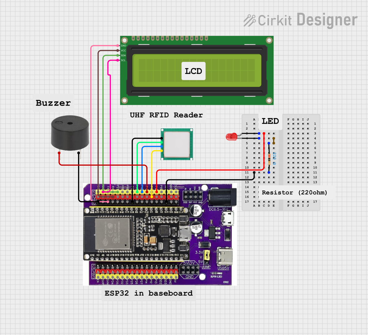
This document provides a detailed overview of a circuit that includes an ESP32 microcontroller, a red LED, a buzzer, a UHF RFID module, a 16x2 I2C LCD, and a resistor. The circuit is designed to interface these components with the ESP32 to perform various functions such as displaying information on the LCD, reading RFID tags, and providing visual and auditory feedback.
Component List
LED: Two Pin (red)
- Description: A red LED with two pins: anode and cathode.
- Pins: anode, cathode
Esp32 on Baseboard
- Description: A versatile microcontroller with multiple GPIO pins and communication interfaces.
- Pins: GPIO23, GPIO22, GPIO1/TX, GPIO3/RX, GPIO21, GPIO19, GPIO18, GPIO5, GPIO17, GPIO16, GPIO4, GPIO0, GPIO2, GPIO15, SD1, SD0, CLK, V, G, GPIO36, GPIO39, GPIO34, GPIO35, GPIO32, GPIO33, GPIO25, GPIO26, GPIO27, GPIO14, GPIO12, GPIO13, SD2, SD3, GND, 5V, 3V, TX, RX, VCC, D22, D21
Buzzer
- Description: A simple buzzer with two pins: PIN and GND.
- Pins: PIN, GND
UHF RFID
- Description: A UHF RFID module with four pins: GND, RX, TX, and VCC.
- Pins: GND, RX, TX, VCC
16x2 I2C LCD
- Description: A 16x2 character LCD with I2C interface.
- Pins: GND, VCC, SDA, SCL
Resistor
- Description: A resistor with a resistance of 220 Ohms.
- Pins: pin1, pin2
- Properties: Resistance: 220 Ohms
Wiring Details
LED: Two Pin (red)
- Anode is connected to GPIO2 of the Esp32 on Baseboard.
- Cathode is connected to pin1 of the Resistor.
Resistor
- Pin1 is connected to cathode of the LED: Two Pin (red).
- Pin2 is connected to G of the Esp32 on Baseboard.
Esp32 on Baseboard
- GPIO2 is connected to anode of the LED: Two Pin (red).
- GPIO22 is connected to SCL of the 16x2 I2C LCD.
- GPIO21 is connected to SDA of the 16x2 I2C LCD.
- GPIO17 is connected to RX of the UHF RFID.
- GPIO16 is connected to TX of the UHF RFID.
- GPIO4 is connected to PIN of the buzzer.
- V is connected to VCC of the 16x2 I2C LCD.
- V is connected to VCC of the UHF RFID.
- G is connected to GND of the buzzer.
- G is connected to GND of the 16x2 I2C LCD.
- G is connected to GND of the UHF RFID.
Buzzer
- PIN is connected to GPIO4 of the Esp32 on Baseboard.
- GND is connected to G of the Esp32 on Baseboard.
UHF RFID
- RX is connected to GPIO17 of the Esp32 on Baseboard.
- TX is connected to GPIO16 of the Esp32 on Baseboard.
- VCC is connected to V of the Esp32 on Baseboard.
- GND is connected to G of the Esp32 on Baseboard.
16x2 I2C LCD
- SCL is connected to GPIO22 of the Esp32 on Baseboard.
- SDA is connected to GPIO21 of the Esp32 on Baseboard.
- VCC is connected to V of the Esp32 on Baseboard.
- GND is connected to G of the Esp32 on Baseboard.
Code
No code is provided for this circuit.