
Arduino UNO Solar-Powered Servo Motor Control System with LCD Display
View and Edit Project In Cirkit Designer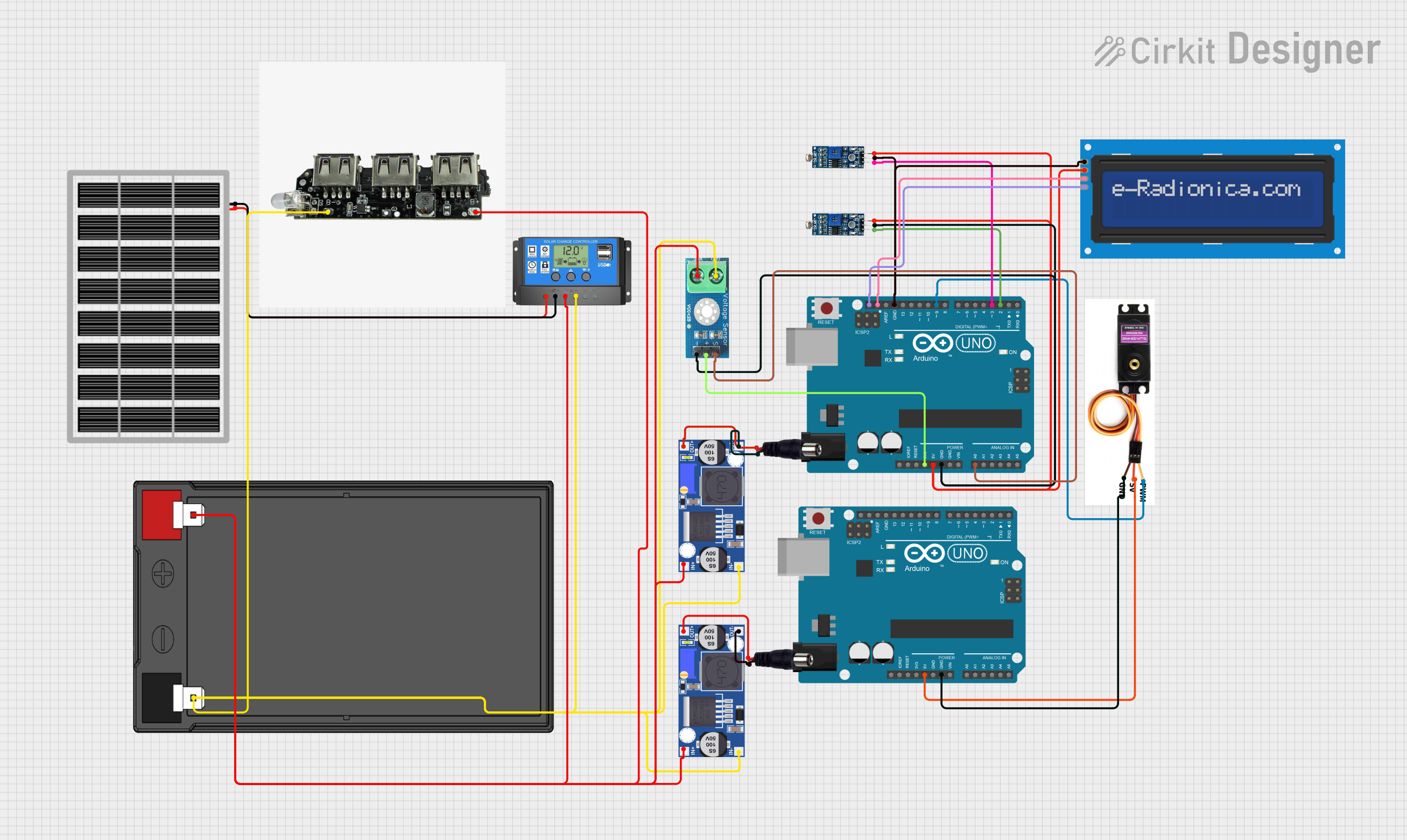
Circuit Documentation
Summary
This document provides a detailed overview of a circuit that includes various components such as Arduino UNO microcontrollers, a servo motor, a power jack, buck converters, a USB power bank module, an LCD screen, a solar charge controller, LDR modules, a voltage sensor, a battery, and a solar panel. The circuit is designed to interface these components to achieve a specific functionality, which is controlled by the Arduino UNO microcontrollers.
Component List
Arduino UNO
- Description: A microcontroller board based on the ATmega328P.
- Pins: UNUSED, IOREF, Reset, 3.3V, 5V, GND, Vin, A0, A1, A2, A3, A4, A5, SCL, SDA, AREF, D13, D12, D11, D10, D9, D8, D7, D6, D5, D4, D3, D2, D1, D0
Servo Motor MG996R
- Description: A high-torque servo motor.
- Pins: PMW, VCC 5V, GND
Power Jack
- Description: A standard power jack for connecting external power sources.
- Pins: POSITIF, NEGATIF
Buck Converter
- Description: A DC-DC converter that steps down voltage.
- Pins: IN+, IN-, OUT+, OUT-
DIY Triple USB Power Bank Module
- Description: A module for providing USB power.
- Pins: -VE TERMINAL, +VE TERMINAL
LCD Screen 16x2 I2C
- Description: A 16x2 character LCD screen with I2C interface.
- Pins: SCL, SDA, VCC, GND
Solar Charge Controller
- Description: A controller for managing solar panel charging.
- Pins: Solar Cell +, Solar Cell -, Battery +, Battery -, Load +, Load -
LDR Module 3 Pin
- Description: A light-dependent resistor module.
- Pins: VCC, GND, DO
12V 7Ah Battery
- Description: A 12V, 7Ah rechargeable battery.
- Pins: 12v +, 12v -
Solar Panel
- Description: A solar panel for generating electricity.
- Pins: gnd, vcc
Voltage Sensor DC 25V
- Description: A sensor for measuring DC voltage up to 25V.
- Pins: +, -, output, gnd, vcc
Wiring Details
Arduino UNO
- 3.3V connected to Voltage Sensor DC 25V (+)
- 5V connected to LDR Module 3 Pin (VCC), LDR Module 3 Pin (VCC), LCD Screen 16x2 I2C (VCC)
- GND connected to LDR Module 3 Pin (GND), Voltage Sensor DC 25V (-), LDR Module 3 Pin (GND), LCD Screen 16x2 I2C (GND)
- A0 connected to Voltage Sensor DC 25V (output)
- SCL connected to LCD Screen 16x2 I2C (SCL)
- SDA connected to LCD Screen 16x2 I2C (SDA)
- D9 connected to Servo Motor MG996R (PMW)
- D3 connected to LDR Module 3 Pin (DO)
- D2 connected to LDR Module 3 Pin (DO)
Servo Motor MG996R
- PMW connected to Arduino UNO (D9)
- VCC 5V connected to Arduino UNO (5V)
- GND connected to Arduino UNO (GND)
Power Jack
- POSITIF connected to Buck Converter (OUT+)
- NEGATIF connected to Buck Converter (OUT-)
Buck Converter
- IN+ connected to Solar Charge Controller (Battery +), DIY Triple USB Power Bank Module (+VE TERMINAL), Voltage Sensor DC 25V (vcc), 12V 7Ah Battery (12v +)
- IN- connected to Solar Charge Controller (Battery -), DIY Triple USB Power Bank Module (-VE TERMINAL), Voltage Sensor DC 25V (gnd), 12V 7Ah Battery (12v -)
- OUT+ connected to Power Jack (POSITIF)
- OUT- connected to Power Jack (NEGATIF)
DIY Triple USB Power Bank Module
- +VE TERMINAL connected to Buck Converter (IN+)
- -VE TERMINAL connected to Buck Converter (IN-)
LCD Screen 16x2 I2C
- SCL connected to Arduino UNO (SCL)
- SDA connected to Arduino UNO (SDA)
- VCC connected to Arduino UNO (5V)
- GND connected to Arduino UNO (GND)
Solar Charge Controller
- Battery + connected to Buck Converter (IN+)
- Battery - connected to Buck Converter (IN-)
- Solar Cell + connected to Solar Panel (vcc)
- Solar Cell - connected to Solar Panel (gnd)
LDR Module 3 Pin
- VCC connected to Arduino UNO (5V)
- GND connected to Arduino UNO (GND)
- DO connected to Arduino UNO (D3)
12V 7Ah Battery
- 12v + connected to Buck Converter (IN+)
- 12v - connected to Buck Converter (IN-)
Solar Panel
- gnd connected to Solar Charge Controller (Solar Cell -)
- vcc connected to Solar Charge Controller (Solar Cell +)
Voltage Sensor DC 25V
- + connected to Arduino UNO (3.3V)
- - connected to Arduino UNO (GND)
- output connected to Arduino UNO (A0)
- gnd connected to Buck Converter (IN-)
- vcc connected to Buck Converter (IN+)
Documented Code
Arduino UNO (Instance 1)
void setup() {
  // put your setup code here, to run once:

}

void loop() {
  // put your main code here, to run repeatedly:

}
Arduino UNO (Instance 2)
void setup() {
  // put your setup code here, to run once:

}

void loop() {
  // put your main code here, to run repeatedly:

}
This documentation provides a comprehensive overview of the circuit, including the components used, their wiring details, and the code running on the microcontrollers.