Arduino UNO Based Fall Detection System with SMS Alerts Using ADXL345 and SIM800L
Circuit Documentation
Summary
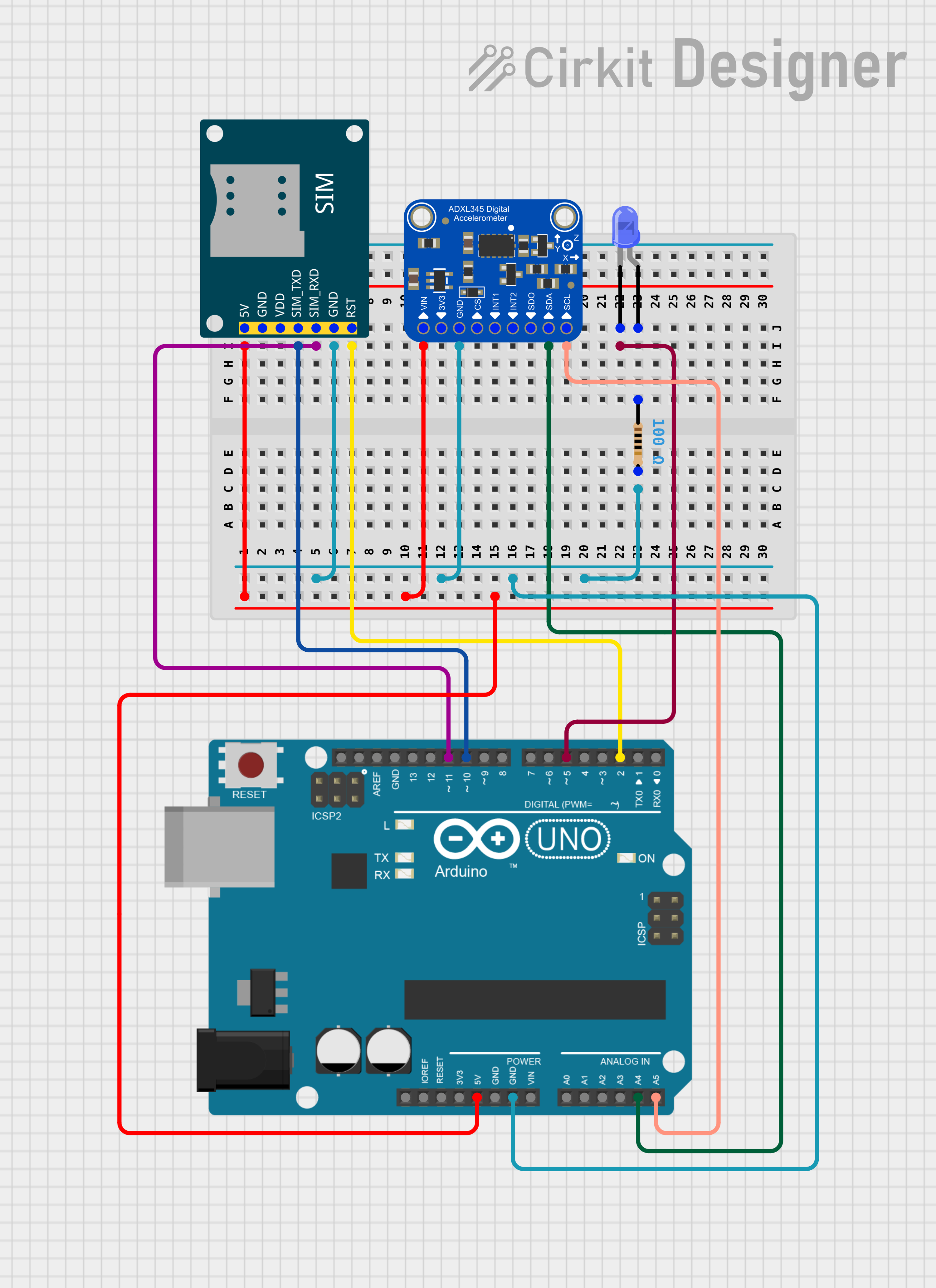
This circuit integrates an Arduino UNO microcontroller with an Adafruit ADXL345 accelerometer, a SIM800L GSM module, and a blue LED with a series resistor. The Arduino UNO is responsible for controlling the accelerometer and GSM module, as well as driving the LED. The accelerometer is used to detect fall conditions, and upon detection, the GSM module sends an SMS alert. The LED serves as an indicator, presumably to signal the detection of a fall or other significant event.
Component List
Arduino UNO
- Microcontroller board based on the ATmega328P
- It has 14 digital input/output pins, 6 analog inputs, a 16 MHz quartz crystal, a USB connection, a power jack, an ICSP header, and a reset button.
Adafruit ADXL345
- A small, thin, low power, 3-axis MEMS accelerometer with high resolution (13-bit) measurement at up to ±16g.
- Digital output data is formatted as 16-bit twos complement and is accessible through either a SPI (3- or 4-wire) or I2C digital interface.
SIM800L GSM Module
- A complete Quad-band GSM/GPRS solution in an LGA package that can be embedded in customer applications.
- Supports features like voice, SMS, data, and fax in a small form factor design.
LED: Two Pin (blue)
- A basic blue LED for indication purposes.
- Typically has a forward voltage drop of about 3.2V to 3.8V and requires a current-limiting resistor to prevent damage.
Resistor
- A passive two-terminal electrical component that implements electrical resistance as a circuit element.
- In this circuit, a 100 Ohm resistor is used, likely for current limiting to the blue LED.
Wiring Details
Arduino UNO
- 5V pin is connected to the 5V power supply lines for the Adafruit ADXL345 and SIM800L GSM Module.
- GND pin is connected to the common ground line shared with the Adafruit ADXL345, SIM800L GSM Module, and the 100 Ohm resistor.
- Digital pins D10 and D11 are connected to the SIM800L GSM Module's SIM_TXD and SIM_RXD respectively, for serial communication.
- Digital pin D2 is connected to the SIM800L GSM Module's RST pin for reset control.
- Analog pins A4 and A5 are connected to the Adafruit ADXL345's SDA/SDIO and SCL pins respectively, for I2C communication.
- Digital pin D5 is connected to the cathode of the blue LED.
Adafruit ADXL345
- VIN pin is connected to the 5V power supply line.
- GND pin is connected to the common ground line.
- SDA/SDIO pin is connected to the Arduino UNO's A4 pin for I2C data.
- SCL pin is connected to the Arduino UNO's A5 pin for I2C clock.
SIM800L GSM Module
- 5V pin is connected to the 5V power supply line.
- GND pin is connected to the common ground line.
- SIM_TXD pin is connected to the Arduino UNO's D10 pin for serial transmission.
- SIM_RXD pin is connected to the Arduino UNO's D11 pin for serial reception.
- RST pin is connected to the Arduino UNO's D2 pin for reset control.
LED: Two Pin (blue)
- Cathode is connected to the Arduino UNO's D5 pin.
- Anode is connected to one end of the 100 Ohm resistor.
Resistor
- One end is connected to the anode of the blue LED.
- The other end is connected to the common ground line.
Documented Code
#include <Wire.h>
#include <Adafruit_Sensor.h>
#include <Adafruit_ADXL345_U.h>
#include <SoftwareSerial.h>

Adafruit_ADXL345_Unified accel = Adafruit_ADXL345_Unified(12345);

SoftwareSerial gsm(11, 10);  // RX, TX for GSM Module

void setup() {
  Serial.begin(9600);
  gsm.begin(9600);

  if(!accel.begin()) {
    Serial.println("No ADXL345 sensor detected");
    while(1);
  }
  accel.setRange(ADXL345_RANGE_16_G);

  // Initialize GSM module
  gsm.println("AT"); // Test the GSM module
  delay(1000);
}

void sendSMS() {
  gsm.println("AT+CMGF=1");  // Set SMS mode to text
  delay(100);
  gsm.println("AT+CMGS=\"+919664939499\"");  // Replace with your phone number
  delay(100);
  gsm.print("Fall Detected!");  // Message content
  delay(100);
  gsm.write(26);  // Send Ctrl+Z to end SMS
  delay(1000);
}

void loop() {
  sensors_event_t event;
  accel.getEvent(&event);

  // Detect fall condition
  if (abs(event.acceleration.x) > 10 || abs(event.acceleration.y) > 10 || abs(event.acceleration.z) < 2) {
    sendSMS();  // Send SMS when fall is detected
    delay(5000);  // Prevent multiple SMS from being sent too frequently
  }
}
This code initializes the ADXL345 accelerometer and the GSM module. It continuously checks for a fall condition based on the accelerometer readings. If a fall is detected, it sends an SMS alert using the GSM module. The sendSMS function is responsible for sending the SMS message. The phone number and message content can be customized as needed.