Cirkit Designer
Your all-in-one circuit design IDE
Home /
Project Documentation
Battery-Powered Raspberry Pi Robotic Arm with Camera
Circuit Documentation
Summary
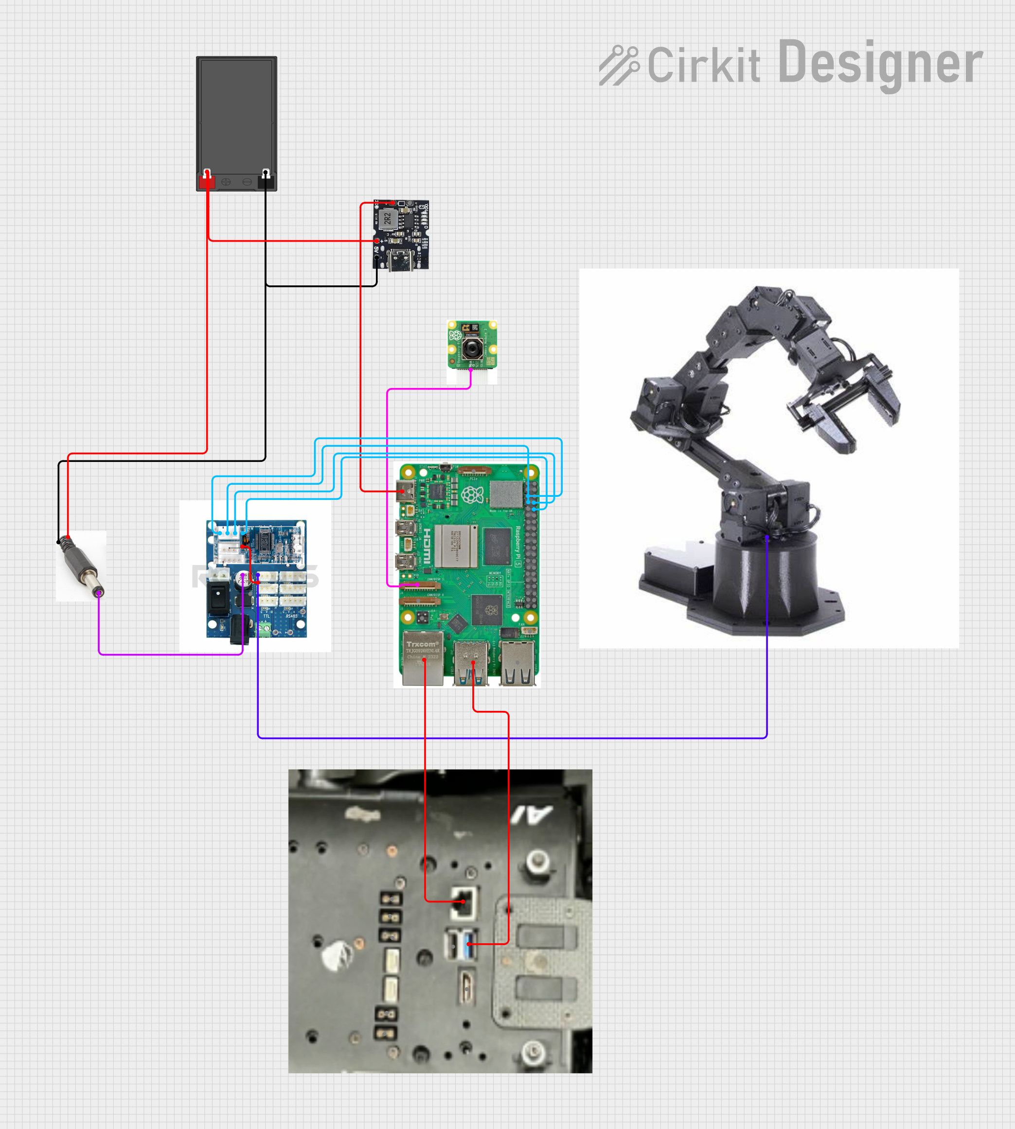
This document provides a detailed overview of a circuit involving a Raspberry Pi 5, a camera module, a power bank module, a robot arm, and various other components. The circuit is designed to power the Raspberry Pi and its peripherals, interface with a camera module, and control a robot arm through a U2D2 interface.
Component List
Raspberry Pi 5
- Description: A single-board computer used for various applications.
- Pins: Type-C, Micro HDMI 1, Micro HDMI 2, Camera 1, Camera 2, PoE, Fan, PCIe, USB 3.0, USB 2.0, Ethernet, 5V, GND, 3.3v, GPIO 14, GPIO 15, GPIO 18, GPIO 23, GPIO 24, GPIO 25, GPIO 8, GPIO 7, GPIO 1, GPIO 12, GPIO 16, GPIO 20, GPIO 21, GPIO 2, GPIO 3, GPIO 4, GPIO 17, GPIO 27, GPIO 22, GPIO 10, GPIO 9, GPIO 11, GPIO 0, GPIO 5, GPIO 6, GPIO 13, GPIO 19, GPIO 26
Battery
- Description: Provides power to the circuit.
- Pins: -, +
Camera Module 3
- Description: A camera module for capturing images and videos.
- Pins: Camera pin
U2D2 PHB
- Description: Interface for controlling the robot arm.
- Pins: servo pin, battery pin, power source
Type-C Power Bank Module
- Description: Provides power to the Raspberry Pi and other components.
- Pins: Gnd, +Ve (Bat), +5v
Robot Arm
- Description: A robotic arm controlled via the U2D2 interface.
- Pins: PHB connector
Power Jack
- Description: Connects the battery to the power bank module.
- Pins: positive terminal, negative terminal, connector terminal
Plate
- Description: Provides additional connectivity options for the Raspberry Pi.
- Pins: Ethernet, USB 3.0, USB 2.0, HDMI, connector, connector
ROBOTIS U2D2
- Description: Interface for controlling the robot arm.
- Pins: USB connector, PHB connector, pin1, pin2, pin3, pin4
Wiring Details
Raspberry Pi 5
- Type-C connected to Type-C Power Bank Module (+Ve (Bat))
- Camera 1 connected to Camera Module 3 (Camera pin)
- USB 3.0 connected to Plate (USB 3.0)
- Ethernet connected to Plate (Ethernet)
- GPIO 14 connected to ROBOTIS U2D2 (pin3)
- GPIO 15 connected to ROBOTIS U2D2 (pin4)
- GPIO 3 connected to ROBOTIS U2D2 (pin1)
- GPIO 4 connected to ROBOTIS U2D2 (pin2)
Battery
- - connected to Power Jack (negative terminal) and Type-C Power Bank Module (Gnd)
- + connected to Power Jack (positive terminal) and Type-C Power Bank Module (+5v)
Camera Module 3
- Camera pin connected to Raspberry Pi 5 (Camera 1)
U2D2 PHB
- servo pin connected to Robot Arm (PHB connector)
- battery pin connected to ROBOTIS U2D2 (PHB connector)
- power source connected to Power Jack (connector terminal)
Type-C Power Bank Module
- Gnd connected to Battery (-) and Power Jack (negative terminal)
- +Ve (Bat) connected to Raspberry Pi 5 (Type-C)
- +5v connected to Battery (+) and Power Jack (positive terminal)
Robot Arm
- PHB connector connected to U2D2 PHB (servo pin)
Power Jack
- positive terminal connected to Battery (+) and Type-C Power Bank Module (+5v)
- negative terminal connected to Battery (-) and Type-C Power Bank Module (Gnd)
- connector terminal connected to U2D2 PHB (power source)
Plate
- USB 3.0 connected to Raspberry Pi 5 (USB 3.0)
- Ethernet connected to Raspberry Pi 5 (Ethernet)
ROBOTIS U2D2
- pin1 connected to Raspberry Pi 5 (GPIO 3)
- pin2 connected to Raspberry Pi 5 (GPIO 4)
- pin3 connected to Raspberry Pi 5 (GPIO 14)
- pin4 connected to Raspberry Pi 5 (GPIO 15)
- PHB connector connected to U2D2 PHB (battery pin)
Code
No code is provided for this circuit.