Cirkit Designer
Your all-in-one circuit design IDE
Home /
Project Documentation
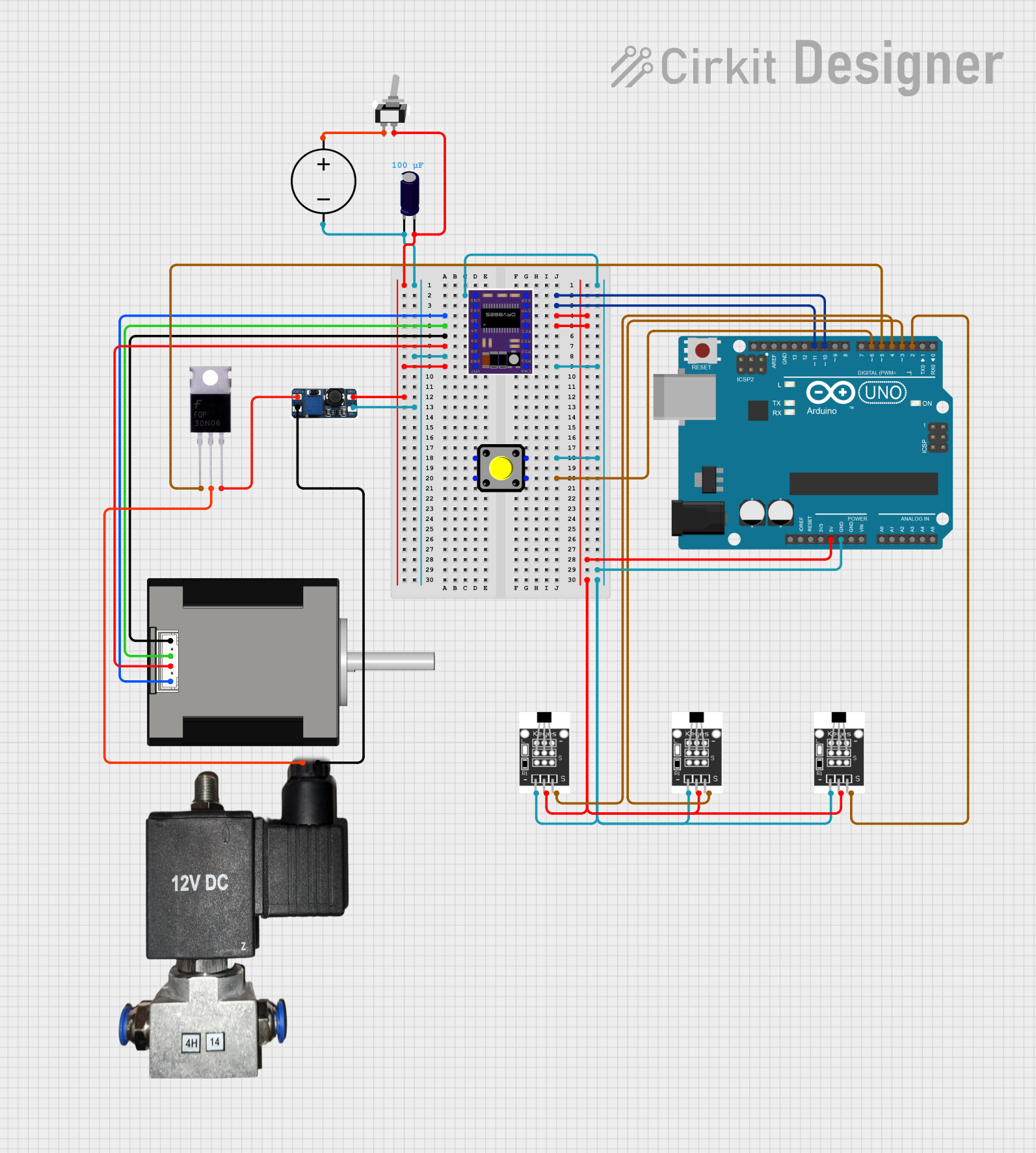
Arduino-Controlled DRV8825 Stepper Motor Driver with Hall Effect Sensing and Pneumatic Actuation

Circuit Documentation
Summary
This circuit is designed to control a Nema 17 stepper motor using a DRV8825 stepper motor driver, which is interfaced with an Arduino UNO microcontroller. The circuit includes a DC power source, a DC-DC boost converter to step up the voltage, and multiple Hall sensors for position detection. A pushbutton is used for input, and a MOSFET controls a 12V pneumatic solenoid valve. The circuit also features an electrolytic capacitor for voltage smoothing and a toggle switch for power control.
Component List
DRV8825 Stepper Motor Driver
- Description: A motor driver capable of driving a bipolar stepper motor.
- Pins: ENABLE, MS1, MS2, MS3, RESET, SLEEP, STEP, DIR, GND, FAULT, 1B, 1A, 2A, 2B, VMOT
Arduino UNO
- Description: A microcontroller board based on the ATmega328P.
- Pins: UNUSED, IOREF, Reset, 3.3V, 5V, GND, Vin, A0-A5, SCL, SDA, AREF, D0-D13
DC Power Source
- Description: Provides the power for the circuit.
- Pins: Ground, Positive
Nema 17 Stepper Motor (42-STH48)
- Description: A stepper motor used for precise motion control.
- Pins: A2 (black), A1 (green), B2 (red), B1 (blue)
Hall Sensor
- Description: A sensor that detects magnetic fields.
- Pins: -, +, S
Electrolytic Capacitor
- Description: Used for voltage smoothing.
- Pins: -, +
- Properties: Capacitance: 0.0001 Farads
DC-DC Boost Converter
- Description: Steps up the input voltage to a higher output voltage.
- Pins: VIN-, VIN+, VOUT+, VOUT-
MOSFET
- Description: A type of transistor used for switching electronic signals.
- Pins: Gate, Drain, Source
12V Pneumatic Solenoid Valve
- Description: An electrically-controlled valve used for controlling air flow.
- Pins: VCC, GND
Pushbutton
- Description: A simple switch mechanism for control of a machine or process.
- Pins: Pin 1, Pin 2, Pin 3, Pin 4
Toggle Switch SPST
- Description: A single-pole single-throw switch used to control power.
- Pins: L1, COM
Wiring Details
DRV8825 Stepper Motor Driver
- VMOT connected to the positive side of the DC-DC Boost Converter and the Electrolytic Capacitor.
- GND connected to the ground of the DC Power Source, the negative side of the DC-DC Boost Converter, and the Electrolytic Capacitor.
- ENABLE connected to the GND through a Pushbutton.
- DIR connected to Arduino UNO's D10.
- STEP connected to Arduino UNO's D11.
- 1B connected to Nema 17's B1 (blue).
- SLEEP and RESET connected to Arduino UNO's 5V.
- 1A connected to Nema 17's A1 (green).
- 2A connected to Nema 17's A2 (black).
- 2B connected to Nema 17's B2 (red).
Arduino UNO
- GND connected to the GND of DRV8825 and Hall Sensors.
- D10 connected to DRV8825's DIR.
- D11 connected to DRV8825's STEP.
- 5V connected to DRV8825's SLEEP and RESET, and to the positive side of Hall Sensors.
- D6 connected to the Pushbutton.
- D5 connected to the Gate of the MOSFET.
- D4 connected to the Signal pin of one Hall Sensor.
- D3 connected to the Signal pin of another Hall Sensor.
- D2 connected to the Signal pin of the third Hall Sensor.
DC Power Source
- Ground connected to the GND of the Electrolytic Capacitor and the DRV8825.
- Positive connected to the Toggle Switch SPST.
Nema 17 Stepper Motor (42-STH48)
- A2 (black) connected to DRV8825's 2A.
- A1 (green) connected to DRV8825's 1A.
- B2 (red) connected to DRV8825's 2B.
- B1 (blue) connected to DRV8825's 1B.
Hall Sensors
- (-) connected to the GND of Arduino UNO.
- (+) connected to the 5V of Arduino UNO.
- S connected to the D2, D3, and D4 of Arduino UNO.
Electrolytic Capacitor
- (+) connected to the positive side of the DC-DC Boost Converter and the VMOT of DRV8825.
- (-) connected to the ground of the DC Power Source and the GND of DRV8825.
DC-DC Boost Converter
- VIN+ connected to the positive side of the Electrolytic Capacitor and the VMOT of DRV8825.
- VIN- connected to the ground of the DC Power Source and the GND of DRV8825.
- VOUT+ connected to the Source of the MOSFET.
- VOUT- connected to the GND of the 12V Pneumatic Solenoid Valve.
MOSFET
- Gate connected to Arduino UNO's D5.
- Drain connected to the VCC of the 12V Pneumatic Solenoid Valve.
- Source connected to the VOUT+ of the DC-DC Boost Converter.
12V Pneumatic Solenoid Valve
- VCC connected to the Drain of the MOSFET.
- GND connected to the VOUT- of the DC-DC Boost Converter.
Pushbutton
- Pin 2 connected to Arduino UNO's D6.
- Pin 3 connected to the ENABLE of DRV8825.
Toggle Switch SPST
- COM connected to the positive side of the Electrolytic Capacitor and the VMOT of DRV8825.
- L1 connected to the Positive of the DC Power Source.
Documented Code
Arduino UNO Code (sketch.ino)
void setup() {
  // put your setup code here, to run once:

}

void loop() {
  // put your main code here, to run repeatedly:

}
Note: The provided code is a template and does not contain any functional code. It needs to be populated with the logic to control the DRV8825, read the Hall sensors, and operate the MOSFET for the solenoid valve.