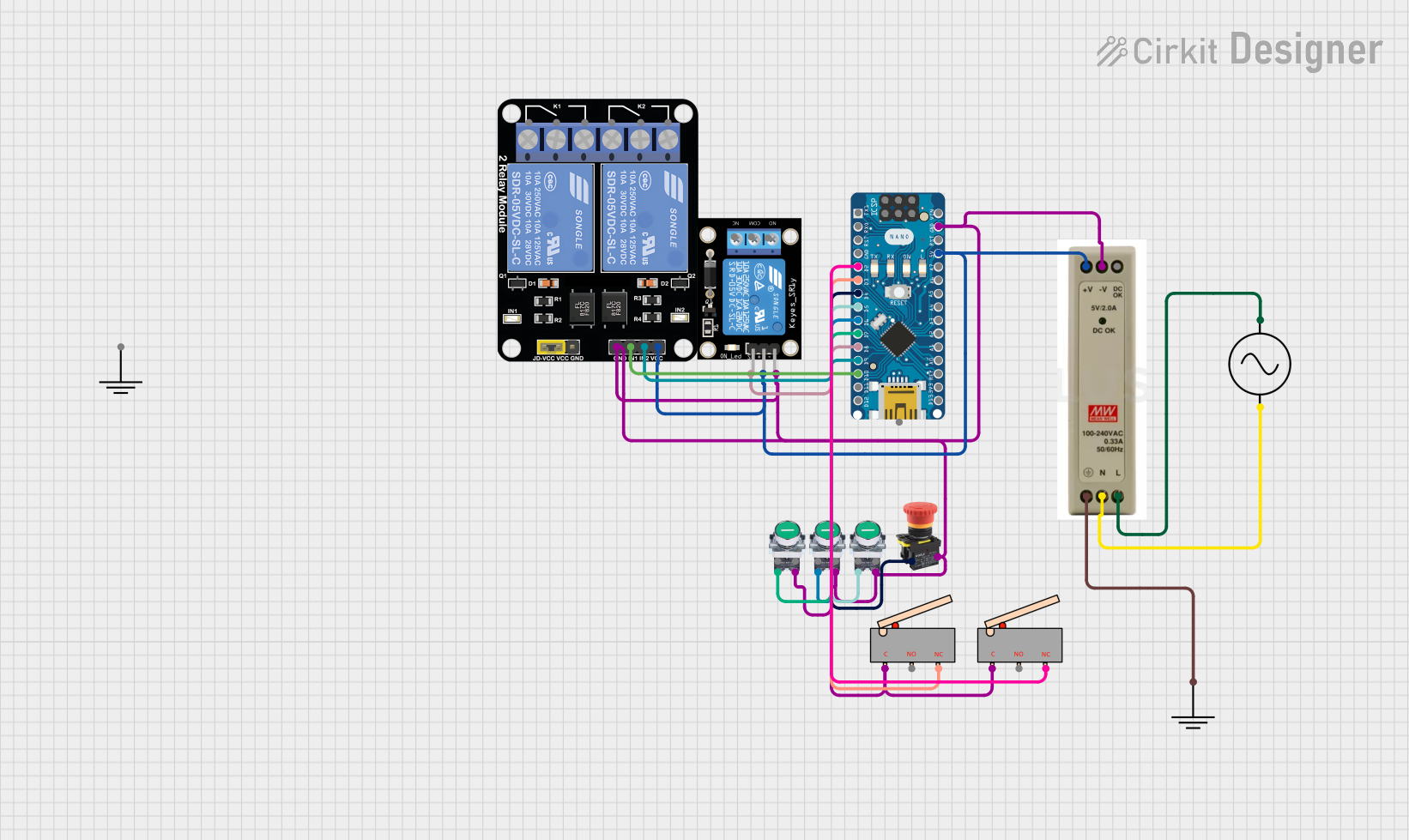
Arduino Nano Controlled Relay System with Safety Interlocks

Circuit Documentation
Summary
This circuit incorporates a variety of components including relay modules, limit switches, pushbuttons, an emergency stop button, a 5V power supply unit (PSU), an AC supply, and an Arduino Nano microcontroller. The circuit is designed to control and interface with various input devices (switches and buttons) and output devices (relays) through the Arduino Nano. The relays can be used to control higher power devices, while the limit switches and pushbuttons provide input to the Arduino for processing and decision-making.
Component List
Relay Module 2 Channel
- Description: A relay module with two channels that can be used to control high power devices.
- Pins: GND, IN1, IN2, VCC, NC1, COM, NO1, NC2, NO2
KY-019 Relay module 1 channel
- Description: A single-channel relay module for controlling one high power device.
- Pins: S, 5V, GND, NC, COM, NO
Limit Switch
- Description: A switch that is actuated by the motion of a machine part or presence of an object.
- Pins: C, NO, NC
Pushbutton START
- Description: A momentary pushbutton used to start a process or operation.
- Pins: NC, NO
Emergency STOP
- Description: A fail-safe control switch that provides immediate shutdown of equipment in an emergency.
- Pins: NC
5V PSU
- Description: A power supply unit that provides a regulated 5V output.
- Pins: 5V+, GND, 5V OK, PE, N, L
AC Supply
- Description: An alternating current (AC) power source.
- Pins: +ve, -ve
Arduino Nano
- Description: A small, complete, and breadboard-friendly microcontroller board based on the ATmega328.
- Pins: D1/TX, D0/RX, RESET, GND, D2, D3, D4, D5, D6, D7, D8, D9, D10, D11/MOSI, D12/MISO, VIN, 5V, A7, A6, A5, A4, A3, A2, A1, A0, AREF, 3V3, D13/SCK
GND
- Description: A ground reference point in the circuit.
- Pins: GND
Wiring Details
Relay Module 2 Channel
- GND: Connected to system ground.
- IN1: Controlled by Arduino Nano pin D10.
- IN2: Controlled by Arduino Nano pin D9.
- VCC: Connected to 5V power supply.
KY-019 Relay module 1 channel
- S: Controlled by Arduino Nano pin D8.
- 5V: Connected to 5V power supply.
- GND: Connected to system ground.
Limit Switch
- C: Connected to system ground.
- NC: One connected to Arduino Nano pin D2, another to pin D3.
Pushbutton START
- NO: One connected to Arduino Nano pin D5, another to pin D6, and another to pin D7.
Emergency STOP
- NC: Connected to Arduino Nano pin D4.
5V PSU
- 5V+: Provides 5V to the circuit.
- GND: Connected to system ground.
- PE: Connected to GND.
- N: Connected to AC Supply -ve.
- L: Connected to AC Supply +ve.
AC Supply
- +ve: Connected to 5V PSU L.
- -ve: Connected to 5V PSU N.
Arduino Nano
- GND: Connected to system ground.
- 5V: Connected to 5V power supply.
- D2, D3, D4, D5, D6, D7, D8, D9, D10: Connected to various components as detailed above.
Documented Code
Arduino Nano - sketch.ino
void setup() {
  // put your setup code here, to run once:

}

void loop() {
  // put your main code here, to run repeatedly:

}
Arduino Nano - documentation.txt
(No additional documentation provided for the code)
This concludes the documentation for the provided circuit. The code for the Arduino Nano is currently a template with empty setup and loop functions, which should be filled with the logic required to control the circuit based on the inputs from the switches and buttons, and to drive the relay modules accordingly.