
Solar-Powered Automated Irrigation System with Soil Moisture Sensing and TFT Display Interface
View and Edit Project In Cirkit Designer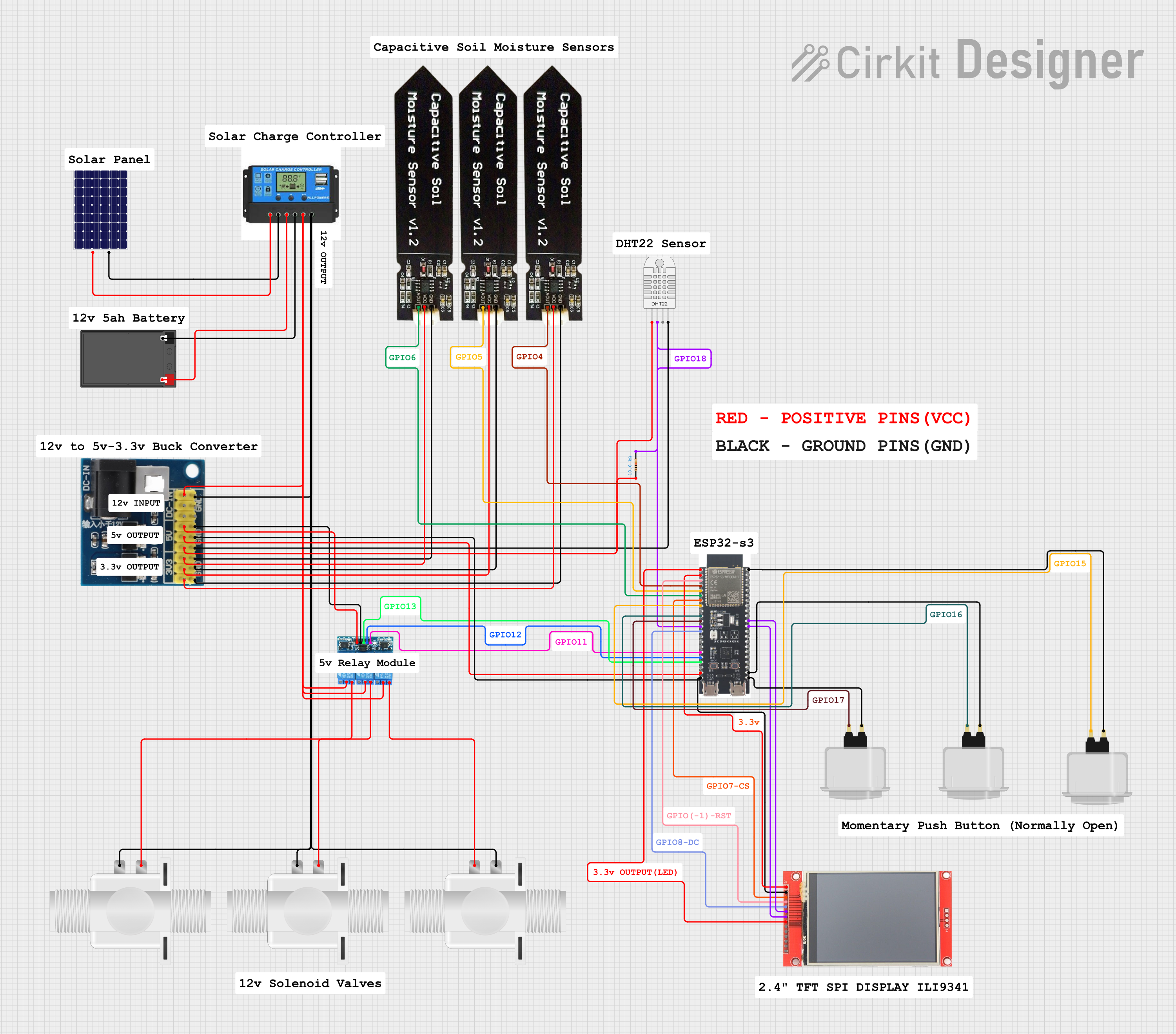
Solar-Powered Automated Irrigation System Documentation
Summary
This document describes the design and wiring of a solar-powered automated irrigation system. The system is designed to harness solar energy to power an irrigation control system that operates solenoid valves based on soil moisture levels. The core of the control system is an ESP32-S3 microcontroller, which interfaces with soil moisture sensors, a DHT22 temperature and humidity sensor, and a TFT display for user interaction. The system uses a charge controller to manage power from the solar panel to the battery and the load. A voltage regulator steps down the voltage to power the microcontroller and sensors. The system also includes a 3-channel relay module to control the solenoid valves.
Component List
Solar Panel
- Description: A photovoltaic panel that converts sunlight into electrical energy.
- Pins:
+,-
Charge Controller
- Description: Manages the power from the solar panel to charge the battery and supply the load.
- Pins:
Solar Positive,Solar Negative,Battery Positive,Battery Negative,Load Positive,Load Negative
Battery
- Description: Stores electrical energy for use when solar power is insufficient.
- Pins:
+,-
Voltage Regulator (12v to 5v/3v)
- Description: Steps down the voltage from the battery to power the microcontroller and sensors.
- Pins:
gnd,dc in1,dc in2,dc in3,v6 5v,v5 5v,v4 5v,v3 3v,v2 3v,v1 3v
3-Channel Relay Module (5V)
- Description: Controls the solenoid valves based on signals from the microcontroller.
- Pins:
COMMON,NO,NC,VCC,GND,CH3,CH2,CH1
Plastic Solenoid Valve
- Description: Controls the flow of water when activated by the relay module.
- Pins:
pin1,pin2
ESP32-S3 Microcontroller
- Description: The brain of the system, it processes sensor data and controls the relays.
- Pins:
3v3,EN,GND,GPIOs,5V
DHT22 Temperature and Humidity Sensor (Wokwi Compatible)
- Description: Measures the ambient temperature and humidity.
- Pins:
VCC,SDA,NC,GND
Resistor (10k Ohms)
- Description: Limits current or divides voltage in the circuit.
- Pins:
pin1,pin2
Capacitive Soil Moisture Sensor V1.2
- Description: Measures the moisture level in the soil.
- Pins:
GND,VCC,AOUT
ILI9341 TFT Display
- Description: Displays system status and sensor readings.
- Pins:
VCC,GND,CS,RESET,DC/RS,SDI,SCK,LED,SDO,T_CLK,T_CS,T_DIN,T_DO,T_IRQ
Arcade Button (White)
- Description: Allows user input to control the system manually.
- Pins:
no name yet
Comments
- Description: Placeholder for additional notes or labels in the circuit design.
Wiring Details
Solar Panel
+connected toSolar Positiveon Charge Controller-connected toSolar Negativeon Charge Controller
Charge Controller
Battery Positiveconnected to+on BatteryBattery Negativeconnected to-on BatteryLoad Positiveconnected toCOMMONon all 3-Channel Relay Modules anddc in1on Voltage RegulatorLoad Negativeconnected toGNDon Voltage Regulator
Battery
+connected toBattery Positiveon Charge Controller-connected toBattery Negativeon Charge Controller
Voltage Regulator (12v to 5v/3v)
gndconnected toGNDon ESP32-S3, DHT22, ILI9341 TFT Display, 3-Channel Relay Module, and all Capacitive Soil Moisture Sensorsdc in1connected toLoad Positiveon Charge Controllerv6 5vconnected toVCCon 3-Channel Relay Modulev5 5vconnected to5Von ESP32-S3v4 5vconnected toVCCon DHT22 through a 10k Ohm Resistorv3 3v,v2 3v,v1 3vconnected toVCCon each Capacitive Soil Moisture Sensor
3-Channel Relay Module (5V)
COMMONconnected toLoad Positiveon Charge ControllerNCconnected topin1on each Plastic Solenoid ValveGNDconnected togndon Voltage RegulatorVCCconnected tov6 5von Voltage RegulatorCH3,CH2,CH1connected toGPIO13,GPIO12,GPIO11on ESP32-S3 respectively
Plastic Solenoid Valve
pin1connected toNCon 3-Channel Relay Modulepin2connected toLoad Negativeon Charge Controller
ESP32-S3 Microcontroller
GNDconnected togndon Voltage Regulator5Vconnected tov5 5von Voltage Regulator3v3connected toVCCandLEDon ILI9341 TFT DisplayENconnected toRESETon ILI9341 TFT DisplayGPIO4,GPIO5,GPIO6connected toAOUTon each Capacitive Soil Moisture SensorGPIO7connected toCSon ILI9341 TFT DisplayGPIO15,GPIO16,GPIO17connected to each Arcade Button (White)GPIO18connected toSDAon DHT22 through a 10k Ohm ResistorGPIO8connected toDC/RSon ILI9341 TFT DisplayGPIO37connected toSDIon ILI9341 TFT DisplayGPIO36connected toSCKon ILI9341 TFT Display
DHT22 Temperature and Humidity Sensor (Wokwi Compatible)
VCCconnected tov4 5von Voltage Regulator through a 10k Ohm ResistorSDAconnected toGPIO18on ESP32-S3GNDconnected togndon Voltage Regulator
Capacitive Soil Moisture Sensor V1.2
VCCconnected tov3 3v,v2 3v,v1 3von Voltage RegulatorAOUTconnected toGPIO4,GPIO5,GPIO6on ESP32-S3GNDconnected togndon Voltage Regulator
ILI9341 TFT Display
VCCconnected to3v3on ESP32-S3GNDconnected togndon Voltage RegulatorCSconnected toGPIO7on ESP32-S3RESETconnected toENon ESP32-S3DC/RSconnected toGPIO8on ESP32-S3SDIconnected toGPIO37on ESP32-S3SCKconnected toGPIO36on ESP32-S3LEDconnected to3v3on ESP32-S3
Arcade Button (White)
- One pin connected to
GPIO15,GPIO16,GPIO17on ESP32-S3 - Other pin connected to
GNDon ESP32-S3
Documented Code
No code has been provided for the microcontroller. The system's functionality depends on the embedded code that would typically handle sensor data processing, control logic for the relay module, user interface management on the TFT display, and any communication protocols used. The code would be documented here once available, including setup routines, main loop logic, interrupt service routines, and any libraries or external modules used.