
Arduino-Controlled Robotics Platform with NRF24L01 Wireless Communication
View and Edit Project In Cirkit Designer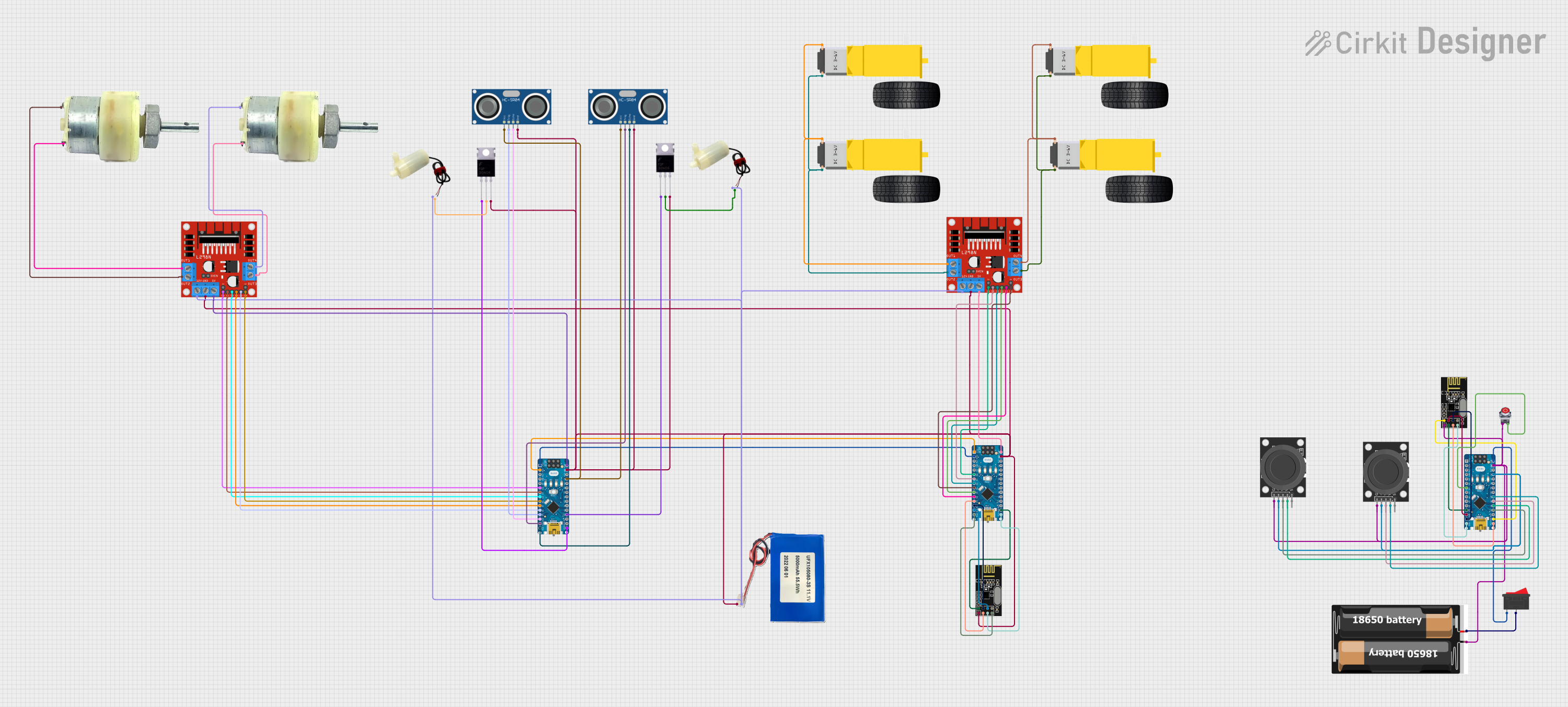
Circuit Documentation
Summary
This circuit is designed to control a robotic vehicle with wireless communication capabilities. It includes two Arduino Nano microcontrollers, one acting as a transmitter with joystick inputs and a pushbutton, and the other as a receiver controlling motor drivers and a sprayer system. The NRF24L01 modules enable wireless communication between the Arduinos. The circuit also features motor drivers for vehicle movement, ultrasonic sensors for distance measurement, MOSFETs for pump control, and a power supply system with a rocker switch.
Component List
Microcontrollers
- Arduino Nano: A compact microcontroller board based on the ATmega328P, featuring digital and analog I/O pins.
Communication Modules
- NRF24L01: A 2.4GHz wireless transceiver module used for wireless communication between the Arduinos.
Motor Drivers
- L298N DC Motor Driver: A high-power motor driver capable of driving DC motors with directional and speed control.
Sensors
- HC-SR04 Ultrasonic Sensor: An ultrasonic ranging module for distance measurement.
Actuators
- 5V Mini Water Pump: A small pump used for spraying operations.
- 12V Geared Motor: A DC motor with a gearbox for increased torque.
- Gearmotor DC Wheels: Motors used for the vehicle's wheels.
Power Supply
- Li-ion 5000mAh Battery: A rechargeable battery providing power to the circuit.
- 2x 18650 Battery Holder: A holder for two 18650 batteries.
- Rocker Switch: A switch to control the power supply to the circuit.
Control Inputs
- KY-023 Dual Axis Joystick Module: A joystick module for user input.
- Pushbutton STOP: A normally open pushbutton used for emergency stops or other control functions.
Power Control
- Mosfet: A type of transistor used for switching electronic signals.
Wiring Details
Arduino Nano (Transmitter)
- Digital Pins:
- D4: Connected to the STOP pushbutton.
- D9: Connected to the CE pin of the NRF24L01 module.
- D10: Connected to the CSN pin of the NRF24L01 module.
- D11/MOSI: Connected to the MOSI pin of the NRF24L01 module.
- D12/MISO: Connected to the MISO pin of the NRF24L01 module.
- D13/SCK: Connected to the SCK pin of the NRF24L01 module.
- Analog Pins:
- A0: Connected to the VRx pin of the first KY-023 joystick module.
- A1: Connected to the VRy pin of the first KY-023 joystick module.
- A2: Connected to the VRx pin of the second KY-023 joystick module.
- A3: Connected to the VRy pin of the second KY-023 joystick module.
- Power Pins:
- 3V3: Connected to the VCC (3V) pin of the NRF24L01 module.
- 5V: Connected to the +5V pins of the KY-023 joystick modules.
- GND: Connected to the GND pins of the KY-023 joystick modules, NRF24L01 module, and the STOP pushbutton.
- VIN: Connected to the rocker switch for power input.
Arduino Nano (Receiver)
- Digital Pins:
- D3: Connected to the ENA and ENB pins of the L298N motor driver for speed control.
- D4 to D8: Connected to the IN1 to IN4 pins of the L298N motor driver for direction control.
- D9 to D12: Connected to the HC-SR04 ultrasonic sensors' TRIG and ECHO pins.
- D13/SCK: Connected to the gate of a MOSFET for pump control.
- Analog Pins:
- A0: Connected to the gate of a MOSFET for pump control.
- Power Pins:
- 3V3: Not used in this configuration.
- 5V: Connected to the VCC pins of the HC-SR04 ultrasonic sensors.
- GND: Connected to the GND pins of the L298N motor driver, HC-SR04 ultrasonic sensors, and the MOSFETs.
- VIN: Connected to the 5V pin of the L298N motor driver for power input.
NRF24L01
- Connected to the corresponding pins on the Arduino Nanos for wireless communication.
L298N DC Motor Driver
- Motor Control Pins:
- ENA, ENB: Connected to the D3 pin of the Arduino Nano for speed control.
- IN1 to IN4: Connected to the D4 to D8 pins of the Arduino Nano for direction control.
- Motor Output Pins:
- OUT1 to OUT4: Connected to the terminals of the 12V geared motors and gearmotor DC wheels.
- Power Pins:
- 12V: Connected to the positive pin of the Li-ion battery and the 5V mini water pumps.
- 5V: Connected to the VIN pin of the Arduino Nano.
- GND: Connected to the GND pins of the Arduino Nano and the MOSFETs.
HC-SR04 Ultrasonic Sensor
- Control Pins:
- TRIG: Connected to the D9 to D11 pins of the Arduino Nano.
- ECHO: Connected to the D10 to D12 pins of the Arduino Nano.
- Power Pins:
- VCC: Connected to the 5V pin of the Arduino Nano.
- GND: Connected to the GND pin of the Arduino Nano.
Mosfet
- Control Pin:
- Gate: Connected to the D13/SCK and A0 pins of the Arduino Nano for pump control.
- Power Pins:
- Drain: Connected to the negative pins of the 5V mini water pumps.
- Source: Connected to the GND of the Li-ion battery and the GND pins of the L298N motor driver.
Power Supply
- Li-ion 5000mAh Battery: Provides 11.1V to the circuit.
- 2x 18650 Battery Holder: Holds two 18650 batteries and provides power to the circuit.
- Rocker Switch: Controls the power supply from the batteries to the Arduino Nano.
Documented Code
Arduino Nano (Transmitter) Code
#include <SPI.h>
#include <nRF24L01.h>
#include <RF24.h>

// Pin assignments for joysticks, button, and NRF24L01
#define JOYSTICK1_X A0
#define JOYSTICK1_Y A1
#define JOYSTICK2_X A2
#define JOYSTICK2_Y A3
#define BUTTON_PIN 4

RF24 radio(9, 10); // CE, CSN
const byte address[6] = "00001";

// Data structure to send data for motion, sprayer control, and button state
struct DataPackage {
  int joystick1_x;
  int joystick1_y;
  int joystick2_x;
  int joystick2_y;
  bool button;
};

DataPackage data;

void setup() {
  // Initialize joysticks and button
  pinMode(JOYSTICK1_X, INPUT);
  pinMode(JOYSTICK1_Y, INPUT);
  pinMode(JOYSTICK2_X, INPUT);
  pinMode(JOYSTICK2_Y, INPUT);
  pinMode(BUTTON_PIN, INPUT_PULLUP);

  // Initialize NRF24L01
  radio.begin();
  radio.openWritingPipe(address);
  radio.setPALevel(RF24_PA_MIN);
  radio.stopListening();
}

void loop() {
  // Read values from the first joystick for motion control
  data.joystick1_x = analogRead(JOYSTICK1_X);
  data.joystick1_y = analogRead(JOYSTICK1_Y);

  // Read values from the second joystick for sprayer control
  data.joystick2_x = analogRead(JOYSTICK2_X);
  data.joystick2_y = analogRead(JOYSTICK2_Y);

  // Read the button state (pressed or not)
  data.button = !digitalRead(BUTTON_PIN); // Button is active low

  // Send the data package via NRF24L01
  radio.write(&data, sizeof(DataPackage));

  // Small delay to avoid overwhelming the receiver
  delay(50);
}
Arduino Nano (Receiver) Code
#include <SPI.h>
#include <nRF24L01.h>
#include <RF24.h>

RF24 radio(9, 10); // CE, CSN

const byte address[6] = "00001";

struct DataPacket {
  int joy1X;
  int joy1Y;
  int joy2X;
  int joy2Y;
  bool buttonState;
};

DataPacket data;

void setup() {
  Serial.begin(9600);
  radio.begin();
  radio.openReadingPipe(0, address);
  radio.setPALevel(RF24_PA_MIN);
  radio.startListening();
}

void loop() {
  if (radio.available()) {
    radio.read(&data, sizeof(DataPacket));

    // Send data to the second Arduino via Serial
    Serial.write((uint8_t*)&data, sizeof(DataPacket));
  }

  delay(100); // Adjust delay as needed
}