
ESP32-Controlled LED Dimmer with Blink Mode and Adjustable Brightness
View and Edit Project In Cirkit Designer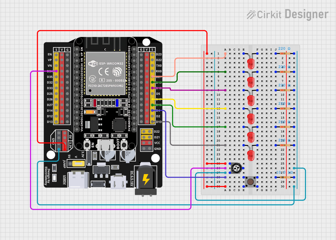
Circuit Documentation
Summary of the Circuit
This circuit is designed to control a series of red LEDs using an ESP32 microcontroller. The LEDs can be turned on to a specific brightness level, which is adjustable via a potentiometer. Additionally, a pushbutton is included to toggle between a blinking mode and a steady-on mode for the LEDs. The brightness level and blinking speed are also controlled by the potentiometer. The ESP32 microcontroller is programmed to read the analog value from the potentiometer and the digital state of the pushbutton to adjust the LED behavior accordingly.
Component List
LEDs
- LED: Two Pin (red): These are standard red LEDs with two pins: an anode and a cathode.
Resistors
- Resistor (220 Ohms): These resistors are used to limit the current through the LEDs to prevent damage.
- Resistor (10,000 Ohms): This resistor is used as a pull-up or pull-down for the pushbutton.
Trimmer Potentiometer
- Trimmer Potentiometer (10,000 Ohms): This adjustable resistor is used to vary the voltage applied to the analog input of the ESP32, which in turn controls the brightness of the LEDs and the blinking speed.
Pushbutton
- Pushbutton: A simple tactile switch that toggles the blinking mode of the LEDs when pressed.
ESP32 - Expansion Board
- ESP32 - Expansion Board: A microcontroller board based on the ESP32 chip, featuring a variety of digital and analog pins for interfacing with various components.
Wiring Details
LEDs
- LED: Two Pin (red)
- Anode: Connected to individual GPIO pins on the ESP32 (D15, D16, D17, D18, D19, D21).
- Cathode: Connected to one side of the corresponding 220 Ohm resistors.
Resistors
Resistor (220 Ohms)
- Pin1: Connected to the cathode of the corresponding LED.
- Pin2: Connected to the ground (G) pin on the ESP32.
Resistor (10,000 Ohms)
- Pin1: Connected to one of the output pins of the pushbutton.
- Pin2: Connected to the ground (G) pin on the ESP32.
Trimmer Potentiometer
- Trimmer Potentiometer (10,000 Ohms)
- Leg1: Connected to the 3.3V pin on the ESP32.
- Wiper: Connected to the analog input pin (D34) on the ESP32.
- Leg2: Connected to the ground (G) pin on the ESP32 through a network of resistors.
Pushbutton
- Pushbutton
- Pin 1 (in): Connected to the 3.3V pin on the ESP32.
- Pin 3 (out): Connected to the digital input pin (D4) on the ESP32.
- Pin 4 (out): Connected to one side of the 10,000 Ohm resistor.
ESP32 - Expansion Board
- ESP32 - Expansion Board
- D15, D16, D17, D18, D19, D21: Connected to the anodes of the LEDs.
- D34: Connected to the wiper of the potentiometer.
- D4: Connected to the pushbutton.
- 3.3V: Connected to the potentiometer and pushbutton.
- G: Connected to the cathodes of the LEDs through resistors and to the potentiometer.
Documented Code
#define NUM_LEDS 6 // Define the number of LEDs used
const int ledPins[NUM_LEDS] = {15, 16, 17, 18, 19, 21}; // Pins for LEDs
const int potPin = 34;        // Pin for potentiometer
const int buttonPin = 4;      // Pin for pushbutton
bool blinkMode = false;       // Variable to determine blinking mode
int brightness = 0;           // Variable to store LED brightness level
int delayTime = 100;          // Delay time for blinking speed

void setup() {
  // Set each LED pin as an output
  for (int i = 0; i < NUM_LEDS; i++) {
    pinMode(ledPins[i], OUTPUT); // Set LED pins as OUTPUT
  }
  pinMode(buttonPin, INPUT_PULLDOWN); // Set button pin as input with pull-down resistor
  Serial.begin(9600); // Start serial communication for debugging
}

void loop() {
  // Read the position of the potentiometer
  int potValue = analogRead(potPin); // Read the analog value from the potentiometer
  brightness = map(potValue, 0, 4095, 0, 255); // Map the potentiometer value from 0-4095 to a range of 0-255

  // Check the status of the pushbutton
  if (digitalRead(buttonPin) == HIGH) {
    blinkMode = true;  // Activate blinking mode if button is pressed
  } else {
    blinkMode = false; // Deactivate blinking mode, return to always-on mode
  }

  if (blinkMode) {
    // Blinking mode alternating forward
    for (int i = 0; i < NUM_LEDS; i++) {
      analogWrite(ledPins[i], brightness); // Turn on LED with appropriate brightness
      delay(delayTime); // Wait according to the delay time
      analogWrite(ledPins[i], 0); // Turn off LED
    }

    // Blinking mode alternating backward
    for (int i = NUM_LEDS - 1; i >= 0; i--) {
      analogWrite(ledPins[i], brightness); // Turn on LED with appropriate brightness
      delay(delayTime); // Wait according to the delay time
      analogWrite(ledPins[i], 0); // Turn off LED
    }

  } else {
    // Always-on mode with brightness controlled by potentiometer
    for (int i = 0; i < NUM_LEDS; i++) {
      analogWrite(ledPins[i], brightness); // Set all LEDs to a constant brightness
    }
  }
  // Display blinking mode status and brightness value on the serial monitor
  Serial.print(blinkMode);
  Serial.print(" : ");
  Serial.println(brightness);
  delay(100); // Wait a moment before repeating the loop
}
This code is designed to run on an ESP32 microcontroller and controls the brightness and blinking of the LEDs based on the input from a potentiometer and a pushbutton. The setup() function initializes the LED pins, the button pin, and the serial communication. The loop() function reads the potentiometer value to set the brightness, checks the button state to toggle the blinking mode, and then either blinks the LEDs or sets them to a steady brightness based on the mode. The serial output is used for debugging purposes to monitor the current mode and brightness level.