
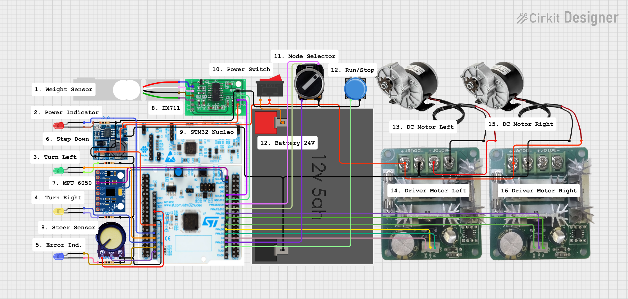
Self-Balancing Scooter Circuit Documentation
Summary
This document provides a detailed overview of the self-balancing scooter circuit. The circuit uses an MPU-6050 sensor to control two DC motors via a STM32 Nucleo F303RE microcontroller. The motors are driven by BDC PWM DC motor controllers. The circuit also includes various LEDs, a potentiometer, a load cell, and a HX711 bridge sensor interface for additional functionalities.
Component List
MPU-6050
- Description: 6-axis motion tracking device
- Pins: VCC, GND, SCL, SDA, XDA, XCL, AD0, INT
Step down Module
- Description: Converts higher voltage to 5V output
- Pins: 24v IN+, GND, 12v IN+, 5v OUT+, 5v OUT-
Potentiometer
- Description: Variable resistor
- Pins: GND, Output, VCC
HX711 - Bridge Sensor Interface
- Description: Load cell amplifier
- Pins: E+, E-, A-, A+, B-, B+, GND - GROUND, DATA (OUT), SCK - CLOCK (IN), 3.3/3.5V Supply
LED: Two Pin (red)
- Description: Red LED
- Pins: cathode, anode
LED: Two Pin (green)
- Description: Green LED
- Pins: cathode, anode
LED: Two Pin (yellow)
- Description: Yellow LED
- Pins: cathode, anode
LED: Two Pin (blue)
- Description: Blue LED
- Pins: cathode, anode
BDC PWM DC MOTOR CONTROLLER 10A 6-90V
- Description: Motor controller
- Pins: + power, - power, + motor, - motor, GND, 0-5V, 5V
Resistor
- Description: 200 Ohms resistor
- Pins: pin1, pin2
Load Cell - Red/white/black/green
- Description: Load cell sensor
- Pins: E+, A-, E-, A+
STM32 Nucleo F303RE
- Description: Microcontroller board
- Pins: PC8, PC9, PC6, PB8, PC5, U5V, NC, PA12, PA11, PB12, PB11, GND, PB2, PB1, PB15, PB14, PB13, AGND, PC4, PB9, AVDD, PA5, PA6, PA7, PB6, PC7, PA9, PA8, PB10, PB4, PB5, PB3, PA10, PA2, PA3, D15, D14, D13, D12, D11, D10, D9, D8, D7, D6, D5, D4, D3, D2, D1, D0, IOREF, RESET, +3V3, +5V, VIN, A0, A1, A2, A3, A4, A5, PC11, PD2, E5V, PA0, PA1, PA4, PB0, PC1, PC0, PC3, PC2, VBAT, PF1, PF0, PC15, PC14, PC13, PB7, PA15, PA14, PA13, nC, BOOT0, VDD, PC12, PC19
3 Position Switch
- Description: Switch with three positions
- Pins: 23, 11, 24, 12
Rocker Switch
- Description: On/Off switch
- Pins: 1, 2
Pushbutton
- Description: Momentary pushbutton
- Pins: Pin 2, Pin 1, Pin 3, Pin 4
250W 12V ELECTRIC MOTOR BRUSH MOTOR DC
- Description: DC motor
- Pins: POSITIF, NEGATIF
12v5ah Battery
- Description: 12V battery
- Pins: 12v +, 12v -
Wiring Details
MPU-6050
- SCL connected to D15 of STM32 Nucleo F303RE
- SDA connected to D14 of STM32 Nucleo F303RE
Step down Module
- 5v OUT+ connected to 3.3/3.5V Supply of HX711 - Bridge Sensor Interface
- 5v OUT+ connected to VIN of STM32 Nucleo F303RE
- 5v OUT- connected to GND of STM32 Nucleo F303RE
- 5v OUT- connected to GND - GROUND of HX711 - Bridge Sensor Interface
Potentiometer
- GND connected to +5V of STM32 Nucleo F303RE
- Output connected to A4 of STM32 Nucleo F303RE
- VCC connected to GND - GROUND of HX711 - Bridge Sensor Interface
HX711 - Bridge Sensor Interface
- SCK - CLOCK (IN) connected to D13 of STM32 Nucleo F303RE
- DATA (OUT) connected to D12 of STM32 Nucleo F303RE
- GND - GROUND connected to pin2 of Resistor
- 3.3/3.5V Supply connected to 5v OUT+ of Step down Module
LED: Two Pin (red)
- anode connected to A0 of STM32 Nucleo F303RE
- cathode connected to pin1 of Resistor
LED: Two Pin (green)
- anode connected to A1 of STM32 Nucleo F303RE
- cathode connected to pin1 of Resistor
LED: Two Pin (yellow)
- anode connected to A2 of STM32 Nucleo F303RE
- cathode connected to pin1 of Resistor
LED: Two Pin (blue)
- anode connected to A3 of STM32 Nucleo F303RE
- cathode connected to pin1 of Resistor
BDC PWM DC MOTOR CONTROLLER 10A 6-90V (Instance 1)
- 0-5V connected to D9 of STM32 Nucleo F303RE
- 5V connected to D8 of STM32 Nucleo F303RE
- GND connected to D7 of STM32 Nucleo F303RE
- + power connected to 2 of Rocker Switch
- - power connected to 12v - of 12v5ah Battery
- + motor connected to POSITIF of 250W 12V ELECTRIC MOTOR BRUSH MOTOR DC
- - motor connected to NEGATIF of 250W 12V ELECTRIC MOTOR BRUSH MOTOR DC
BDC PWM DC MOTOR CONTROLLER 10A 6-90V (Instance 2)
- 0-5V connected to D6 of STM32 Nucleo F303RE
- 5V connected to D5 of STM32 Nucleo F303RE
- GND connected to D4 of STM32 Nucleo F303RE
- + power connected to 2 of Rocker Switch
- - power connected to 12v - of 12v5ah Battery
- + motor connected to POSITIF of 250W 12V ELECTRIC MOTOR BRUSH MOTOR DC
- - motor connected to NEGATIF of 250W 12V ELECTRIC MOTOR BRUSH MOTOR DC
3 Position Switch
- 11 connected to D11 of STM32 Nucleo F303RE
- 23 connected to D10 of STM32 Nucleo F303RE
- 24 connected to D3 of STM32 Nucleo F303RE
- 12 connected to GND - GROUND of HX711 - Bridge Sensor Interface
Rocker Switch
- 1 connected to 12v + of 12v5ah Battery
- 2 connected to + power of BDC PWM DC MOTOR CONTROLLER 10A 6-90V
Pushbutton
- Pin 2 connected to D2 of STM32 Nucleo F303RE