Cirkit Designer
Your all-in-one circuit design IDE
Home /
Project Documentation
Battery-Powered IR Sensor and Buzzer Alarm System
Circuit Documentation
Summary
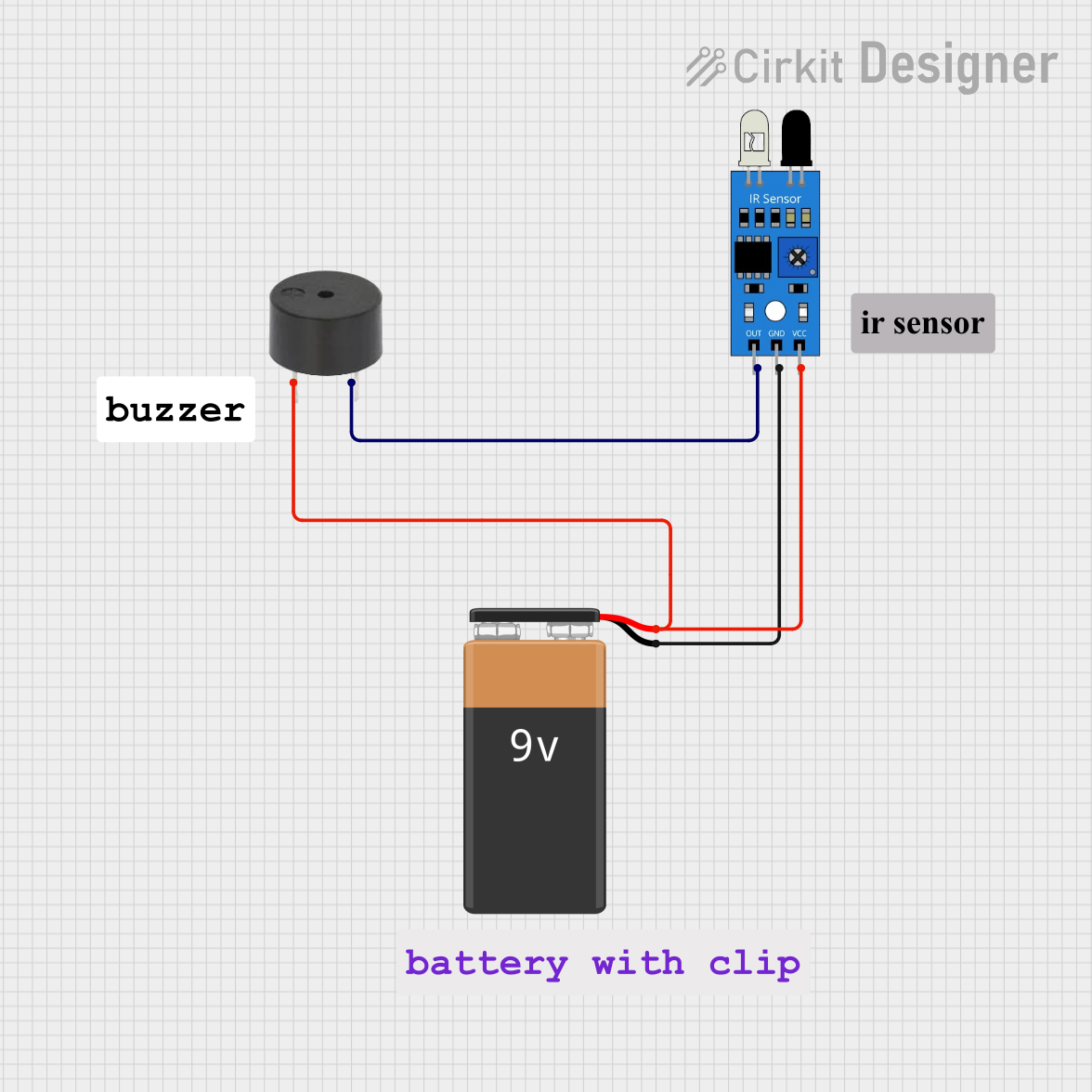
This circuit consists of an IR sensor, a buzzer, and a 9V battery. The IR sensor detects an object and triggers the buzzer to sound an alarm. The circuit is powered by a 9V battery.
Component List
IR Sensor
- Pins: out, gnd, vcc
- Description: Detects infrared light and outputs a signal when an object is detected.
- Purpose in Circuit: To detect objects and send a signal to the buzzer.
Buzzer
- Pins: PIN, GND
- Description: Emits sound when a signal is received.
- Purpose in Circuit: To sound an alarm when triggered by the IR sensor.
9V Battery
- Pins: -, +
- Description: Provides power to the circuit.
- Purpose in Circuit: To supply the necessary voltage to the IR sensor and buzzer.
Wiring Details
IR Sensor
- Pin out is connected to GND of the Buzzer.
- Pin gnd is connected to - of the 9V Battery.
- Pin vcc is connected to PIN of the Buzzer and + of the 9V Battery.
Buzzer
- Pin GND is connected to out of the IR Sensor.
- Pin PIN is connected to vcc of the IR Sensor and + of the 9V Battery.
9V Battery
- Pin - is connected to gnd of the IR Sensor.
- Pin + is connected to vcc of the IR Sensor and PIN of the Buzzer.
Code
There is no microcontroller code associated with this circuit.