
Arduino Mega 2560-Based Hydroponic System with Solar Power and Sensor Monitoring
View and Edit Project In Cirkit Designer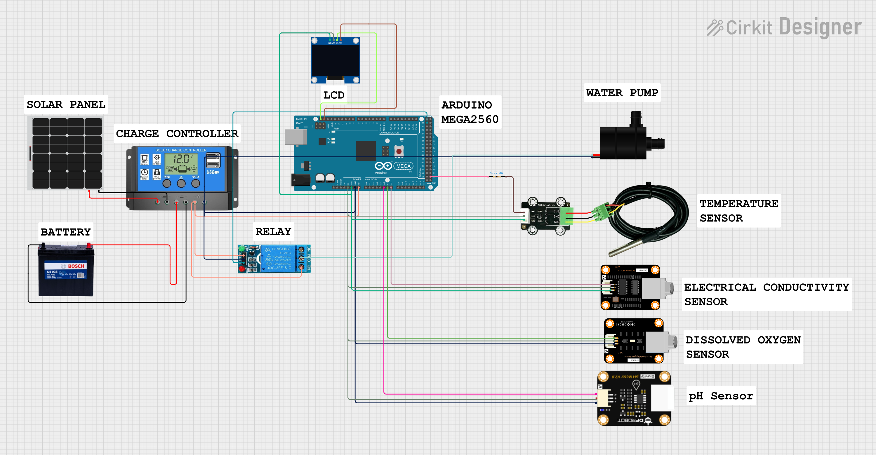
Hydroponic System Circuit Documentation
Summary
This document provides a detailed overview of a hydroponic system circuit. The system includes a solar panel, a battery, a solar charge controller, various sensors (temperature, dissolved oxygen, electrical conductivity, and pH), a water pump, a relay, an OLED display, and an Arduino Mega 2560 microcontroller. The system is designed to monitor and control the hydroponic environment, displaying sensor readings on an OLED display and controlling the water pump based on temperature readings.
Component List
Solar Panel
- Description: Converts sunlight into electrical energy.
- Pins: +, -
12V 200Ah Battery
- Description: Stores electrical energy.
- Pins: GND, 12V
12V SINGLE CHANNEL RELAY
- Description: Controls the water pump.
- Pins: NC, COM, NO, IN, GND, VCC
Solar Charge Controller
- Description: Manages the charging of the battery from the solar panel.
- Pins: Solar Cell +, Solar Cell -, Battery +, Battery -, Load +, Load -
Arduino Mega 2560
- Description: Microcontroller for processing sensor data and controlling the relay.
- Pins: IOREF, RESET, 3V3, 5V, GND, VIN, A0-A15, D0-D53, SDA, SCL, AREF
DFRobot EC Sensor
- Description: Measures electrical conductivity of the nutrient solution.
- Pins: -, +, A
DFRobot Dissolved Oxygen Sensor
- Description: Measures dissolved oxygen levels in the nutrient solution.
- Pins: -, +, A
pH Degree Sensor Module
- Description: Measures the pH level of the nutrient solution.
- Pins: pH Negative, pH Positive, pH A
Water Pump
- Description: Circulates the nutrient solution.
- Pins: VCC, GND
MKE-S15 DS18B20 Waterproof Temperature Sensor
- Description: Measures the temperature of the nutrient solution.
- Pins: SIG, 5V, GND
Resistor
- Description: Used in the temperature sensor circuit.
- Pins: pin1, pin2
- Properties: 4700 Ohms
128x64 OLED Display (I2C IIC SPI Serial)
- Description: Displays sensor readings.
- Pins: GND, SDA, SCL, VCC
Wiring Details
Solar Panel
- + connected to Solar Charge Controller Solar Cell +
- - connected to Solar Charge Controller Solar Cell -
12V 200Ah Battery
- GND connected to Solar Charge Controller Battery -
- 12V connected to Solar Charge Controller Battery +
12V SINGLE CHANNEL RELAY
- COM connected to Water Pump VCC
- NO connected to Solar Charge Controller Load +, Arduino Mega 2560 VIN, 12V SINGLE CHANNEL RELAY VCC
- IN connected to Arduino Mega 2560 D22
- GND connected to Water Pump GND, DFRobot Dissolved Oxygen Sensor -, Solar Charge Controller Load -, pH Degree Sensor Module pH Negative, Arduino Mega 2560 GND
Solar Charge Controller
- Solar Cell + connected to Solar Panel +
- Solar Cell - connected to Solar Panel -
- Battery + connected to 12V 200Ah Battery 12V
- Battery - connected to 12V 200Ah Battery GND
- Load + connected to 12V SINGLE CHANNEL RELAY NO, Arduino Mega 2560 VIN, 12V SINGLE CHANNEL RELAY VCC
- Load - connected to Water Pump GND, DFRobot Dissolved Oxygen Sensor -, pH Degree Sensor Module pH Negative, Arduino Mega 2560 GND, 12V SINGLE CHANNEL RELAY GND
Arduino Mega 2560
- VIN connected to Solar Charge Controller Load +
- GND connected to Solar Charge Controller Load -, Water Pump GND, DFRobot Dissolved Oxygen Sensor -, pH Degree Sensor Module pH Negative, 12V SINGLE CHANNEL RELAY GND
- D22 connected to 12V SINGLE CHANNEL RELAY IN
- A5 connected to pH Degree Sensor Module pH A
- A6 connected to DFRobot Dissolved Oxygen Sensor A
- A7 connected to DFRobot EC Sensor A
- SDA connected to 128x64 OLED Display (I2C IIC SPI Serial) SDA
- SCL connected to 128x64 OLED Display (I2C IIC SPI Serial) SCL
- D53 connected to Resistor pin1
- 5V connected to MKE-S15 DS18B20 Waterproof Temperature Sensor 5V, DFRobot Dissolved Oxygen Sensor +, DFRobot EC Sensor +, 128x64 OLED Display (I2C IIC SPI Serial) VCC, pH Degree Sensor Module pH Positive
DFRobot EC Sensor
- - connected to Arduino Mega 2560 GND
- + connected to Arduino Mega 2560 5V
- A connected to Arduino Mega 2560 A7
DFRobot Dissolved Oxygen Sensor
- - connected to Arduino Mega 2560 GND
- + connected to Arduino Mega 2560 5V
- A connected to Arduino Mega 2560 A6
pH Degree Sensor Module
- pH Negative connected to Arduino Mega 2560 GND
- pH Positive connected to Arduino Mega 2560 5V
- pH A connected to Arduino Mega 2560 A5
Water Pump
- VCC connected to 12V SINGLE CHANNEL RELAY COM
- GND connected to Arduino Mega 2560 GND
MKE-S15 DS18B20 Waterproof Temperature Sensor
- SIG connected to Resistor pin2
- 5V connected to Arduino Mega 2560 5V
- GND connected to Arduino Mega 2560 GND
Resistor
- pin1 connected to Arduino Mega 2560 D53
- pin2 connected to MKE-S15 DS18B20 Waterproof Temperature Sensor SIG
128x64 OLED Display (I2C IIC SPI Serial)
- GND connected to Arduino Mega 2560 GND
- SDA connected to Arduino Mega 2560 SDA
- SCL connected to Arduino Mega 2560 SCL
- VCC connected to Arduino Mega 2560 5V
Code Documentation
/*
 * Arduino Sketch for Hydroponic System
 * This code reads data from temperature, dissolved oxygen (DO), electrical
 * conductivity (EC), and pH sensors, and displays the readings on an LCD
 * screen. The water pump is controlled via a relay.
 */

#include <LiquidCrystal.h>

// Pin definitions
const int tempPin = 53; // Connected via resistor
const int doPin = A6;
const int ecPin = A7;
const int phPin = A5;
const int relayPin = 22;
const int lcdRs = 12, lcdEn = 11, lcdD4 = 5, lcdD5 = 4, lcdD6 = 3, lcdD7 = 2;

// Initialize the LCD library with the numbers of the interface pins
LiquidCrystal lcd(lcdRs, lcdEn, lcdD4, lcdD5, lcdD6, lcdD7);

void setup() {
  // Initialize serial communication
  Serial.begin(9600);
  // Initialize the LCD
  lcd.begin(16, 2);
  // Print a message to the LCD
  lcd.print("Hydroponic System");
  // Set relay pin as output
  pinMode(relayPin, OUTPUT);
  // Turn off the relay initially
  digitalWrite(relayPin, LOW);
}

void loop() {
  // Read sensor values
  int tempValue = analogRead(tempPin);
  int doValue = analogRead(doPin);
  int ecValue = analogRead(ecPin);
  int phValue = analogRead(phPin);

  // Check for sensor read errors
  if (tempValue == -1 || doValue == -1 || ecValue == -1 || phValue == -1) {
    Serial.println("Error reading sensor values");
    lcd.setCursor(0, 0);
    lcd