
Arduino Mega 2560-Based Smart Home Automation System with LCD Display and Sensor Integration
View and Edit Project In Cirkit Designer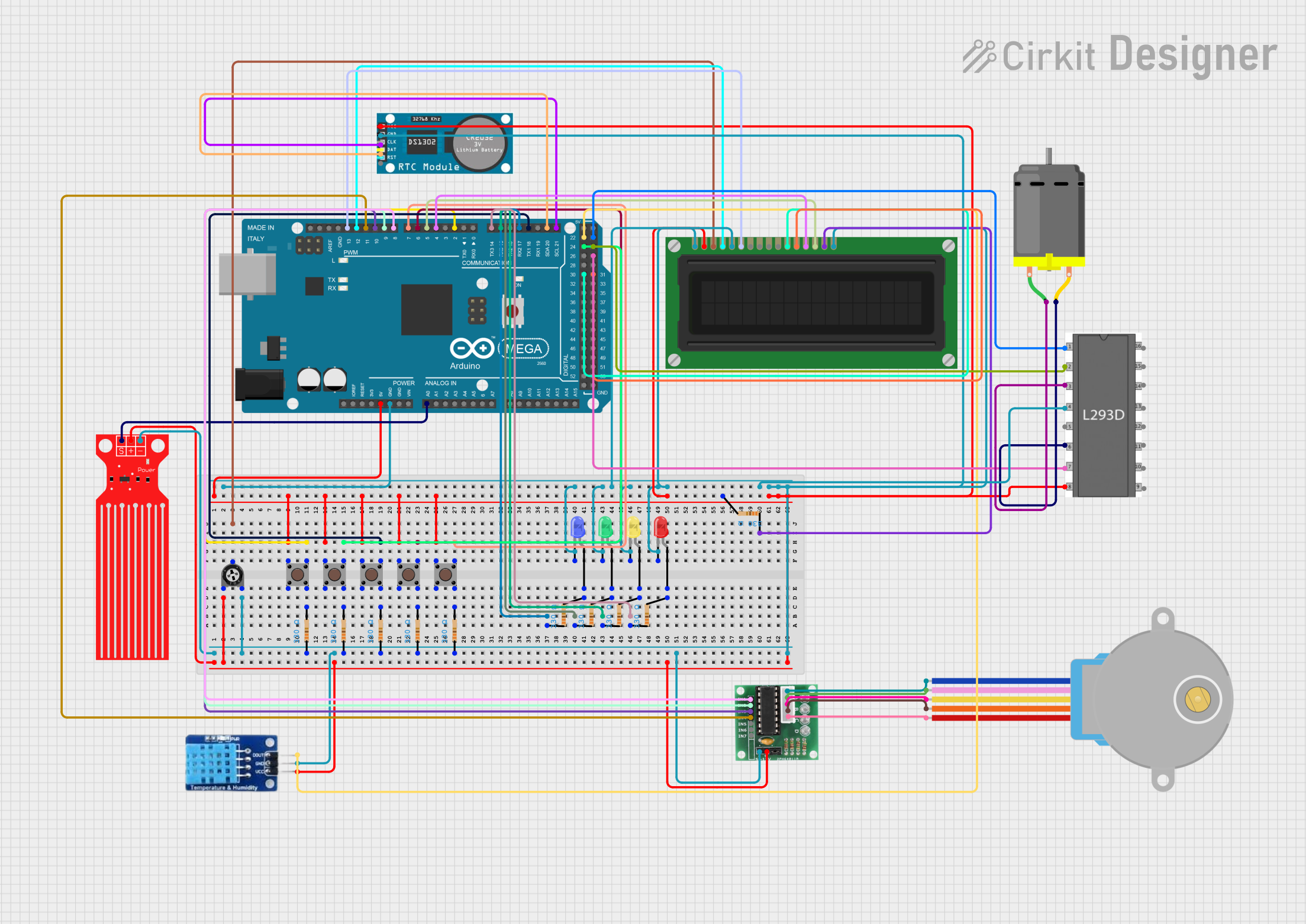
Circuit Documentation
Summary
This circuit is designed using an Arduino Mega 2560 microcontroller to interface with various sensors, actuators, and display components. The circuit includes a DHT11 temperature and humidity sensor, a water level sensor, an LCD display, a real-time clock (RTC), a stepper motor, a DC motor, pushbuttons, LEDs, resistors, a trimmer potentiometer, and motor drivers. The Arduino Mega 2560 serves as the central control unit, processing inputs from sensors and controlling outputs to actuators and displays.
Component List
Arduino Mega 2560
- Description: Microcontroller board based on the ATmega2560.
- Pins: IOREF, RESET, 3V3, 5V, GND, VIN, A0-A15, D0-D53, AREF, SDA, SCL.
DHT11
- Description: Temperature and humidity sensor.
- Pins: DATA, GND, VCC.
LCD Display (16 pin)
- Description: 16x2 character LCD display.
- Pins: VSS, VDD, VO, RS, R_W, E, DB0-DB7, A, K.
Water Level Sensor
- Description: Sensor to detect water level.
- Pins: SIG, VCC, GND.
RTC
- Description: Real-time clock module.
- Pins: VCC, GND, CLK, DAT, RST.
ULN 2003
- Description: Darlington transistor array.
- Pins: IN1-IN7, GND, +, COIL1-COIL5.
DC Motor
- Description: Direct current motor.
- Pins: pin 1, pin 2.
28BYJ-48 Stepper Motor
- Description: 5V stepper motor.
- Pins: BLUE, PINK, YELLOW, ORANGE, RED.
Pushbutton
- Description: Momentary pushbutton switch.
- Pins: Pin 3 (out), Pin 4 (out), Pin 1 (in), Pin 2 (in).
LED: Two Pin (blue)
- Description: Blue LED.
- Pins: cathode, anode.
LED: Two Pin (green)
- Description: Green LED.
- Pins: cathode, anode.
LED: Two Pin (yellow)
- Description: Yellow LED.
- Pins: cathode, anode.
LED: Two Pin (red)
- Description: Red LED.
- Pins: cathode, anode.
Resistor
- Description: Fixed resistor.
- Pins: pin1, pin2.
- Properties: Resistance: 330 Ohms.
Trimmer Potentiometer
- Description: Adjustable resistor.
- Pins: leg1, wiper, leg2.
- Properties: Resistance: 10000 Ohms.
l293d motor driver
- Description: Motor driver IC.
- Pins: enable 1, input 1, output 1, gnd, output 2, input 2, vs, vss, input 4, output 4, output 3, input 3, enable 2.
Wiring Details
Arduino Mega 2560
- 5V: Connected to VCC of Water Level Sensor, DHT11, ULN 2003, LCD Display, RTC, and Trimmer Potentiometer leg1.
- GND: Connected to GND of Water Level Sensor, DHT11, ULN 2003, LCD Display, RTC, and Trimmer Potentiometer leg2.
- D2 PWM: Connected to Pin 3 (out) of Pushbutton.
- D4 PWM: Connected to DB6 of LCD Display.
- D5 PWM: Connected to DB7 of LCD Display.
- D6 PWM: Connected to Pin 3 (out) of Pushbutton.
- D7 PWM: Connected to Pin 3 (out) of Pushbutton.
- D8 PWM: Connected to IN1 of ULN 2003.
- D9 PWM: Connected to IN2 of ULN 2003.
- D10 PWM: Connected to IN3 of ULN 2003.
- D11 PWM: Connected to IN4 of ULN 2003.
- D12 PWM: Connected to RS of LCD Display.
- D13 PWM: Connected to E of LCD Display.
- D14/TX3: Connected to pin1 of Resistor.
- D15/RX3: Connected to pin1 of Resistor.
- D16 PWM/TX2: Connected to pin1 of Resistor.
- D17 PWM/RX2: Connected to pin1 of Resistor.
- D18/TX1: Connected to Pin 3 (out) of Pushbutton.
- D20/SDA: Connected to DAT of RTC.
- D21/SCL: Connected to CLK of RTC.
- D22: Connected to DATA of DHT11.
- D23: Connected to enable 1 of l293d motor driver.
- D24: Connected to Pin 3 (out) of Pushbutton.
- D25: Connected to input 1 of l293d motor driver.
- D27: Connected to input 2 of l293d motor driver.
- D30: Connected to DB4 of LCD Display.
- D31: Connected to DB5 of LCD Display.
- A0: Connected to SIG of Water Level Sensor.
DHT11
- VCC: Connected to 5V of Arduino Mega 2560.
- GND: Connected to GND of Arduino Mega 2560.
- DATA: Connected to D22 of Arduino Mega 2560.
LCD Display (16 pin)
- VDD: Connected to 5V of Arduino Mega 2560.
- VSS: Connected to GND of Arduino Mega 2560.
- VO: Connected to wiper of Trimmer Potentiometer.
- RS: Connected to D12 PWM of Arduino Mega 2560.
- R_W: Connected to GND of Arduino Mega 2560.
- E: Connected to D13 PWM of Arduino Mega 2560.
- DB4: Connected to D30 of Arduino Mega 2560.
- DB5: Connected to D31 of Arduino Mega 2560.
- DB6: Connected to D4 PWM of Arduino Mega 2560.
- DB7: Connected to D5 PWM of Arduino Mega 2560.
- A: Connected to pin2 of Resistor.
- K: Connected to GND of Arduino Mega 2560.
Water Level Sensor
- VCC: Connected to 5V of Arduino Mega 2560.
- GND: Connected to GND of Arduino Mega 2560.
- SIG: Connected to A0 of Arduino Mega 2560.
RTC
- VCC: Connected to 5V of Arduino Mega 2560.
- GND: Connected to GND of Arduino Mega 2560.
- CLK: Connected to D21/SCL of Arduino Mega 2560.
- DAT: Connected to D20/SDA of Arduino Mega 2560.
ULN 2003
- +: Connected to 5V of Arduino Mega 2560.
- GND: Connected to GND of Arduino Mega 2560.
- IN1: Connected to D8 PWM of Arduino Mega 2560.
- IN2: Connected to D9 PWM of Arduino Mega 2560.
- IN3: Connected to D10 PWM of Arduino Mega 2560.
- IN4: Connected to D11 PWM of Arduino Mega 2560.
- COIL1: Connected to BLUE of 28BYJ-48 Stepper Motor.
- COIL2: Connected to PINK of 28BYJ-48 Stepper Motor.
- COIL3: Connected to YELLOW of 28BYJ-48 Stepper Motor.
- COIL4: Connected to ORANGE of 28BYJ-48 Stepper Motor.
- COIL5: Connected to RED of 28BYJ-48 Stepper Motor.
DC Motor
- pin 1: Connected to output 1 of l293d motor driver.
- pin 2: Connected to output 2 of l293d motor driver.
28BYJ-48 Stepper Motor
- BLUE: Connected to COIL1 of ULN 2003.
- PINK: Connected to COIL2 of ULN 2003.
- YELLOW: Connected to COIL3 of ULN 2003.
- ORANGE: Connected to COIL4 of ULN 2003.
- RED: Connected to COIL5 of ULN 2003.
Pushbutton
- Pin 1 (in): Connected to 5V of Arduino Mega 2560.
- **