
Battery-Powered Peltier Module Temperature Control Circuit with LED Indicator
View and Edit Project In Cirkit Designer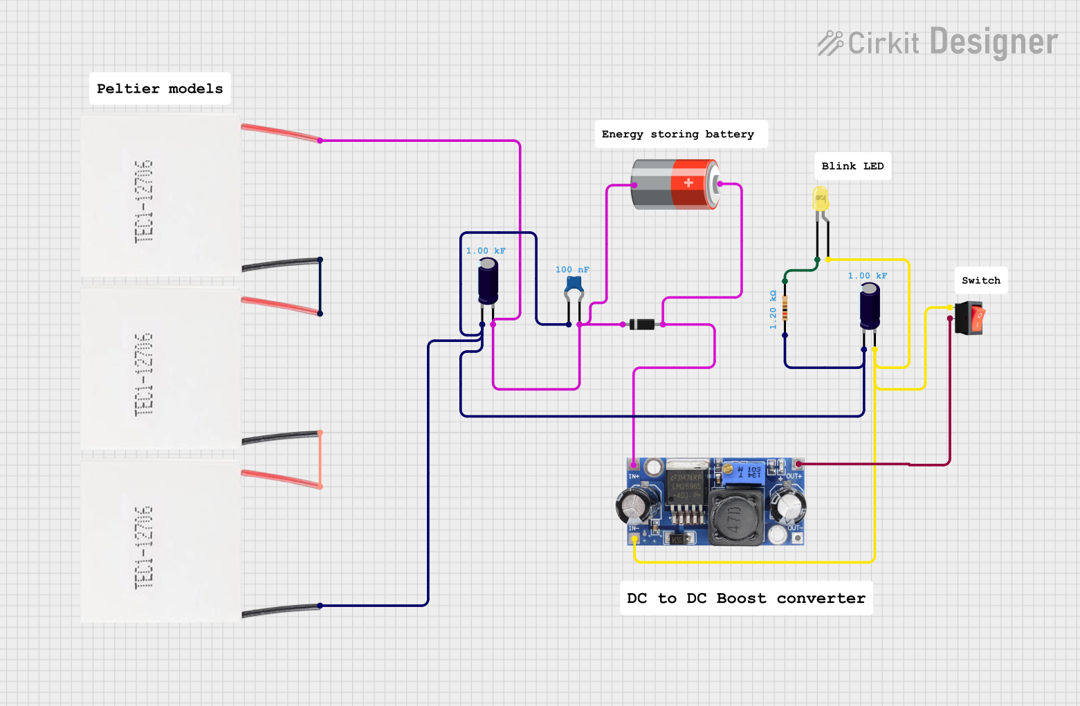
Circuit Documentation
Summary
This document provides a detailed overview of the circuit, including a list of components, their descriptions, wiring details, and any embedded code used in the circuit. The circuit includes various capacitors, resistors, diodes, LEDs, a battery, a DC-DC converter, a rocker switch, and multiple Peltier modules.
Component List
Electrolytic Capacitor
- Description: Electrolytic capacitors are polarized capacitors with a larger capacitance per unit volume than other types.
- Pins: -, +
- Properties:
- Capacitance: 1000 Farads
Ceramic Capacitor
- Description: Ceramic capacitors are non-polarized capacitors with a small capacitance value.
- Pins: pin0, pin1
- Properties:
- Capacitance: 0.0000001 Farads
Diode
- Description: Diodes allow current to flow in one direction only.
- Pins: cathode, anode
Resistor
- Description: Resistors limit the flow of electric current.
- Pins: pin1, pin2
- Properties:
- Resistance: 1200 Ohms
LED: Two Pin (yellow)
- Description: Light Emitting Diodes (LEDs) emit light when current flows through them.
- Pins: cathode, anode
5v Battery
- Description: Provides a 5V power supply.
- Pins: +, -
DC-DC Converter
- Description: Converts DC voltage levels.
- Pins: +VCC IN, GND IN, +VCC OUT, GND OUT
Rocker Switch
- Description: A switch that rocks back and forth to open or close a circuit.
- Pins: output, input
Peltier Module
- Description: A thermoelectric device that heats or cools when current flows through it.
- Pins: Negative, Positive
Wiring Details
Electrolytic Capacitor
- Pins:
- -: Connected to:
- Electrolytic Capacitor (-)
- Ceramic Capacitor (pin0)
- Peltier Module (Negative)
- Resistor (pin1)
- +: Connected to:
- 5v Battery (-)
- Ceramic Capacitor (pin1)
- Diode (cathode)
- Peltier Module (Positive)
- -: Connected to:
Ceramic Capacitor
- Pins:
- pin0: Connected to:
- Electrolytic Capacitor (-)
- pin1: Connected to:
- Electrolytic Capacitor (+)
- 5v Battery (-)
- Diode (cathode)
- pin0: Connected to:
Diode
- Pins:
- cathode: Connected to:
- Electrolytic Capacitor (+)
- Ceramic Capacitor (pin1)
- anode: Connected to:
- 5v Battery (+)
- DC-DC Converter (+VCC IN)
- cathode: Connected to:
Resistor
- Pins:
- pin1: Connected to:
- Electrolytic Capacitor (-)
- pin2: Connected to:
- LED: Two Pin (yellow) (cathode)
- pin1: Connected to:
LED: Two Pin (yellow)
- Pins:
- cathode: Connected to:
- Resistor (pin2)
- anode: Connected to:
- Rocker Switch (input)
- Electrolytic Capacitor (+)
- DC-DC Converter (GND IN)
- cathode: Connected to:
5v Battery
- Pins:
- +: Connected to:
- DC-DC Converter (+VCC IN)
- Diode (anode)
- -: Connected to:
- Electrolytic Capacitor (+)
- Ceramic Capacitor (pin1)
- +: Connected to:
DC-DC Converter
- Pins:
- +VCC IN: Connected to:
- 5v Battery (+)
- Diode (anode)
- GND IN: Connected to:
- LED: Two Pin (yellow) (anode)
- Rocker Switch (input)
- Electrolytic Capacitor (+)
- +VCC OUT: Connected to:
- Rocker Switch (output)
- GND OUT: Not connected
- +VCC IN: Connected to:
Rocker Switch
- Pins:
- input: Connected to:
- LED: Two Pin (yellow) (anode)
- Electrolytic Capacitor (+)
- DC-DC Converter (GND IN)
- output: Connected to:
- DC-DC Converter (+VCC OUT)
- input: Connected to:
Peltier Module
- Pins:
- Negative: Connected to:
- Electrolytic Capacitor (-)
- Peltier Module (Positive)
- Positive: Connected to:
- Electrolytic Capacitor (+)
- Peltier Module (Negative)
- Negative: Connected to:
Code
No embedded code is used in this circuit.
This document provides a comprehensive overview of the circuit, including the components used, their connections, and any relevant properties.