
Arduino Nano-Based Posture Detector with MPU6050 Gyroscopes and Flex Sensor
View and Edit Project In Cirkit Designer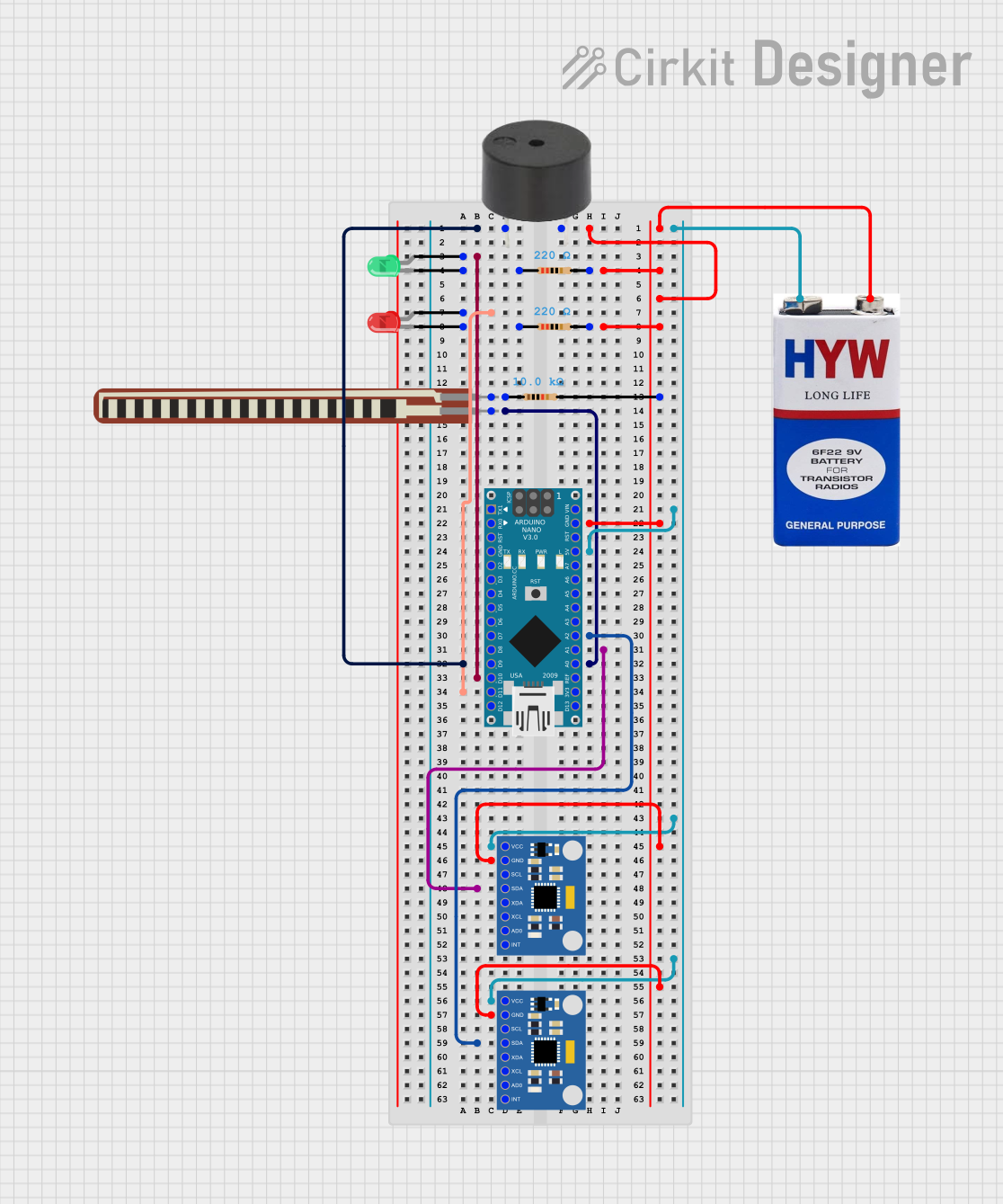
Circuit Documentation
Summary
The circuit is designed to monitor posture using flex and gyroscopic sensors and provide feedback through visual and auditory indicators. It consists of an Arduino Nano microcontroller interfaced with two MPU6050 accelerometer and gyroscope modules, a flex resistor, two LEDs (one red, one green), a buzzer, and three resistors. The Arduino Nano controls the system, reads sensor values, and activates the LEDs and buzzer based on the sensor readings to indicate good or bad posture.
Component List
Resistor (220 Ohms)
- Two resistors with a resistance of 220 Ohms each.
- Used for current limiting for the LEDs.
Resistor (10k Ohms)
- One resistor with a resistance of 10k Ohms.
- Used as a pull-down resistor for the flex sensor.
MPU6050 Accelerometer + Gyroscope (Wokwi Compatible)
- Two MPU6050 modules used for detecting orientation and movement.
2.2 inch Basic Flex Resistor
- A flex sensor that changes resistance based on bending.
Buzzer
- An audible alert device that emits a tone when activated.
LED: Two Pin (red)
- A red LED used as an indicator for incorrect posture.
LED: Two Pin (green)
- A green LED used as an indicator for correct posture.
Arduino Nano
- A microcontroller board based on the ATmega328P.
- It reads sensor values and controls the LEDs and buzzer.
9V Battery
- Provides power to the circuit.
Wiring Details
Buzzer
- PIN connected to Arduino Nano D9.
- GND connected to the common ground net.
LED: Two Pin (green)
- Anode connected to Arduino Nano D10.
- Cathode connected through a 220 Ohm resistor to the common ground net.
LED: Two Pin (red)
- Anode connected to Arduino Nano D11/MOSI.
- Cathode connected through a 220 Ohm resistor to the common ground net.
2.2 inch Basic Flex Resistor
- Pin 2 connected to Arduino Nano A0.
- Pin 1 connected through a 10k Ohm resistor to the common ground net.
MPU6050 Accelerometer + Gyroscope (Wokwi Compatible)
- SDA of one MPU6050 connected to Arduino Nano A1.
- SDA of the other MPU6050 connected to Arduino Nano A2.
- VCC of both MPU6050s connected to the 5V net from the Arduino Nano.
- GND of both MPU6050s connected to the common ground net.
Arduino Nano
- D9, D10, and D11/MOSI used for output control signals.
- A0, A1, and A2 used for sensor inputs.
- 5V and GND pins used for power distribution.
9V Battery
- Positive terminal connected to Arduino Nano VIN.
- Negative terminal connected to the common ground net.
Documented Code
const int FLEX_PIN = A0;
const int GYRO1_PIN = A1;
const int GYRO2_PIN = A2;
const int BUZZER_PIN = 9;
const int LED_GOOD_PIN = 10;
const int LED_WRONG_PIN = 11;

const int FLEX_THRESHOLD = 400;
const int GYRO_THRESHOLD = 20;

int flexValue = 0;
int gyro1Value = 0;
int gyro2Value = 0;
bool goodposture = true;

void setup() {
  Serial.begin(9600);
  pinMode(FLEX_PIN, INPUT);
  pinMode(GYRO1_PIN, INPUT);
  pinMode(GYRO2_PIN, INPUT);
  pinMode(BUZZER_PIN, OUTPUT);
  pinMode(LED_GOOD_PIN, OUTPUT);
  pinMode(LED_WRONG_PIN, OUTPUT);
}

void loop() {
  flexValue = analogRead(FLEX_PIN);
  gyro1Value = analogRead(GYRO1_PIN);
  gyro2Value = analogRead(GYRO2_PIN);

  Serial.print("Flex:");
  Serial.print(flexValue);
  Serial.print(" Gyro_1:");
  Serial.print(gyro1Value);
  Serial.print(" Gyro_2:");
  Serial.println(gyro2Value);

  if ((flexValue < FLEX_THRESHOLD) || (gyro1Value < GYRO_THRESHOLD) || (gyro2Value < GYRO_THRESHOLD)) {
    goodposture = false;
  } else {
    goodposture = true;
  }

  if (!goodposture) {
    digitalWrite(LED_WRONG_PIN, HIGH);
    digitalWrite(LED_GOOD_PIN, LOW);
    tone(BUZZER_PIN, 1000, 500);
  } else {
    digitalWrite(LED_GOOD_PIN, HIGH);
    digitalWrite(LED_WRONG_PIN, LOW);
  }
  delay(100);
}
This code is responsible for reading the values from the flex sensor and the two gyroscopes. If any of the readings fall below the defined thresholds, it indicates bad posture by turning on the red LED, turning off the green LED, and sounding the buzzer. If the posture is good, the green LED is turned on, and the red LED is turned off. The sensor values and status are printed to the serial monitor for debugging purposes.