
Location-Aware IoT Device with GSM Communication and LED Indicators
View and Edit Project In Cirkit Designer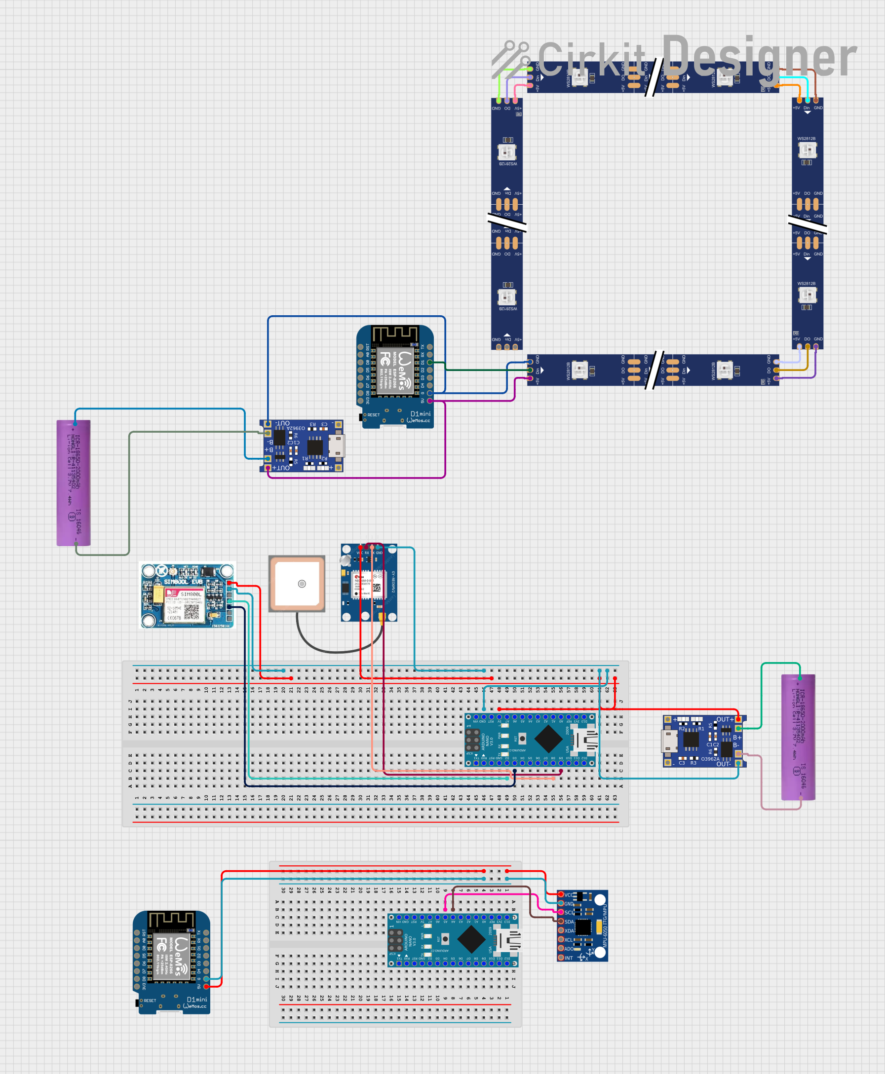
Circuit Documentation
Summary
This circuit integrates various components to achieve a multifunctional system. It includes microcontrollers (Arduino Nano and Wemos D1 Mini), communication modules (SIM 800L GSM and GPS NEO 6M), a motion sensor (MPU-6050), power management modules (TP4056 and Li-ion batteries), and an LED strip (WS2812 RGB). The Arduino Nano is used as the central processing unit, interfacing with the GSM module for cellular communication, the GPS module for location tracking, and the MPU-6050 for motion sensing. The Wemos D1 Mini controls the WS2812 RGB LED strip. Power management is handled by the TP4056 charging modules connected to 18650 Li-ion batteries.
Component List
- WS2812 RGB LED Strip: A digital RGB LED strip that can be controlled via a single data line.
- Arduino Nano: A small, complete, and breadboard-friendly microcontroller board based on the ATmega328P.
- SIM 800L V2.0 GSM: A GSM/GPRS module that allows for cellular communication, including SMS and data.
- Li-ion Battery 18650-2000mAh 3.7V 7.4WH: A rechargeable battery providing power to the circuit.
- TP4056: A lithium battery charging module with battery protection.
- Wemos D1 Mini: A mini Wi-Fi board based on ESP-8266EX.
- GPS NEO 6M: A compact GPS module for location tracking.
- MPU-6050: A motion tracking device with a 3-axis gyroscope and a 3-axis accelerometer.
Wiring Details
WS2812 RGB LED Strip
- 5V: Connected to the 5V output of the TP4056 module and Wemos D1 Mini.
- GND: Connected to the ground (GND) of the TP4056 module and Wemos D1 Mini.
- DIN: Connected to the D1 pin of the Wemos D1 Mini.
- DO: Data output, connected to the next WS2812 RGB LED strip's DIN.
Arduino Nano
- GND: Connected to the ground (GND) of the SIM 800L GSM, GPS NEO 6M, and TP4056 module.
- 5V: Connected to the 5V input of the SIM 800L GSM, GPS NEO 6M, and TP4056 module.
- D2: Connected to the SIM_TXD of the SIM 800L GSM.
- D3: Connected to the SIM.RXD of the SIM 800L GSM.
- D8: Connected to the TX of the GPS NEO 6M.
- D9: Connected to the RX of the GPS NEO 6M.
- A4 (SDA): Connected to the SDA of the MPU-6050.
- A5 (SCL): Connected to the SCL of the MPU-6050.
SIM 800L V2.0 GSM
- SIM_TXD: Connected to D2 of the Arduino Nano.
- SIM.RXD: Connected to D3 of the Arduino Nano.
- 5V/4V: Connected to the 5V output of the TP4056 module.
- GND: Connected to the ground (GND) of the Arduino Nano.
GPS NEO 6M
- VCC: Connected to the 5V output of the TP4056 module.
- RX: Connected to D9 of the Arduino Nano.
- TX: Connected to D8 of the Arduino Nano.
- GND: Connected to the ground (GND) of the Arduino Nano.
MPU-6050
- VCC: Connected to the 5V of the Wemos D1 Mini.
- GND: Connected to the ground (GND) of the Wemos D1 Mini.
- SCL: Connected to A5 (SCL) of the Arduino Nano.
- SDA: Connected to A4 (SDA) of the Arduino Nano.
TP4056
- OUT+: Connected to the 5V input of the Arduino Nano, SIM 800L GSM, GPS NEO 6M, and WS2812 RGB LED strip.
- OUT-: Connected to the ground (GND) of the Arduino Nano, SIM 800L GSM, GPS NEO 6M, and WS2812 RGB LED strip.
- B+: Connected to the positive (+) terminal of the Li-ion battery.
- B-: Connected to the negative (-) terminal of the Li-ion battery.
Wemos D1 Mini
- 5V: Connected to the 5V of the WS2812 RGB LED strip and MPU-6050.
- G: Connected to the ground (GND) of the WS2812 RGB LED strip and MPU-6050.
- D1: Connected to the DIN of the WS2812 RGB LED strip.
Li-ion Battery 18650-2000mAh 3.7V 7.4WH
- +: Connected to the B+ of the TP4056 module.
- -: Connected to the B- of the TP4056 module.
Documented Code
Arduino Nano (Instance ID: 329ae99b-4879-4398-b382-a7e17492c4fd)
void setup() {
  // put your setup code here, to run once:

}

void loop() {
  // put your main code here, to run repeatedly:

}
Arduino Nano (Instance ID: 1e44264f-a0ce-40c0-834e-99fc65223b07)
void setup() {
  // put your setup code here, to run once:

}

void loop() {
  // put your main code here, to run repeatedly:

}
Note: The provided code for both Arduino Nano instances is a template with empty setup and loop functions. Specific functionality needs to be implemented based on the requirements of the circuit's application.