
ESP32-WROOM Bluetooth-Enabled Battery-Powered Button Interface with OLED Display
View and Edit Project In Cirkit Designer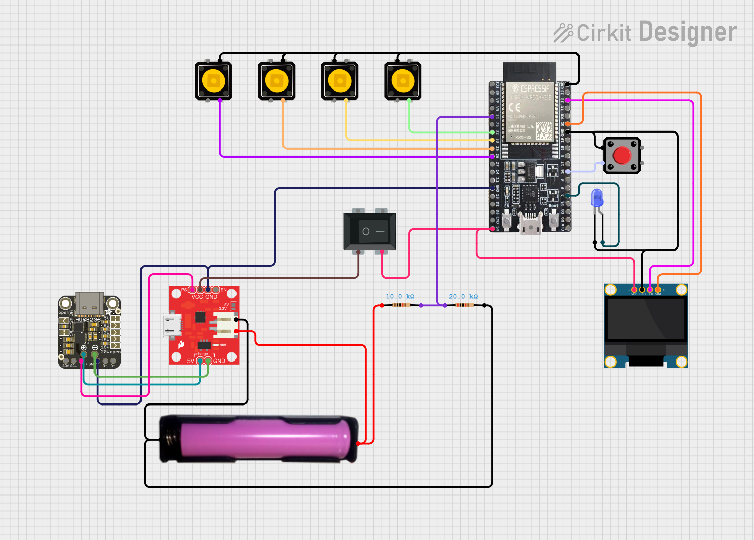
Circuit Documentation
Summary
This circuit is designed to interface an ESP32 microcontroller with various input and output components, including momentary push buttons, a rocker switch, an LED, an OLED display, and a power management system. The ESP32 is programmed to handle Bluetooth communication, display information on the OLED screen, and read battery voltage levels.
Component List
Rocker Switch (4 Pin)
- Pins: 1, 2, 3, 4
- Description: A 4-pin rocker switch used to control power to the circuit.
LED (Blue, Two Pin)
- Pins: Cathode, Anode
- Description: A blue LED used for visual indication.
Momentary Push Button Switch
- Pins: 1, 2, 3, 4
- Description: A 4-pin momentary push button switch used for user input.
18650 Battery in Holder
- Pins: GND, VCC
- Description: A 18650 battery holder providing power to the circuit.
USB Type C Power Delivery Dummy Breakout
- Pins: SDA, SCL, V+, Vout, GND, Data -, Data +
- Description: A USB Type C breakout board for power delivery and I2C communication.
Power Cell - LiPo Charger/Booster
- Pins: JST -, JST +, VCC, GND, 5V, PS, EN
- Description: A LiPo charger and booster module for managing battery power.
Pushbutton
- Pins: Pin 1, Pin 2, Pin 3, Pin 4
- Description: A 4-pin pushbutton used for user input.
ESP32-WROOM
- Pins: 3V3, EN, SP, SN, 34, 35, 32, 33, 25, 26, 27, 14, 12, GND, 13, 23, 22, TX0, RX0, 21, 19, 18, 5, 17, 16, 4, 0, 2, 15, SD1, SD0, CLK, 5V, CMD, SD3, SD2, USB
- Description: A versatile microcontroller with built-in Wi-Fi and Bluetooth capabilities.
OLED 128x64 I2C Monochrome Display
- Pins: VDD, GND, SCK, SDA
- Description: A monochrome OLED display for visual output.
Resistor (10k Ohms)
- Pins: pin1, pin2
- Description: A 10k Ohm resistor used in the voltage divider circuit.
Resistor (20k Ohms)
- Pins: pin1, pin2
- Description: A 20k Ohm resistor used in the voltage divider circuit.
Wiring Details
Rocker Switch (4 Pin)
- Pin 2: Connected to VCC of the Power Cell - LiPo Charger/Booster.
- Pin 4: Connected to 5V of the ESP32-WROOM and VDD of the OLED Display.
LED (Blue, Two Pin)
- Cathode: Connected to GND of the ESP32-WROOM.
- Anode: Connected to Pin 2 of the ESP32-WROOM.
Momentary Push Button Switch
Instance 1
- Pin 1: Connected to Pin 3 of another Momentary Push Button Switch.
- Pin 4: Connected to Pin 32 of the ESP32-WROOM.
Instance 2
- Pin 1: Connected to Pin 3 of another Momentary Push Button Switch.
- Pin 4: Connected to Pin 33 of the ESP32-WROOM.
Instance 3
- Pin 1: Connected to Pin 3 of another Momentary Push Button Switch.
- Pin 4: Connected to Pin 25 of the ESP32-WROOM.
Instance 4
- Pin 1: Connected to Pin 3 of another Momentary Push Button Switch.
- Pin 4: Connected to Pin 26 of the ESP32-WROOM.
18650 Battery in Holder
- GND: Connected to JST - of the Power Cell - LiPo Charger/Booster.
- VCC: Connected to JST + of the Power Cell - LiPo Charger/Booster.
USB Type C Power Delivery Dummy Breakout
- GND: Connected to GND of the Power Cell - LiPo Charger/Booster.
- V+: Connected to PS of the Power Cell - LiPo Charger/Booster.
- Vout: Connected to 5V of the Power Cell - LiPo Charger/Booster.
Power Cell - LiPo Charger/Booster
- GND: Connected to GND of the USB Type C Power Delivery Dummy Breakout.
- VCC: Connected to Pin 2 of the Rocker Switch.
- JST -: Connected to GND of the 18650 Battery in Holder.
- JST +: Connected to VCC of the 18650 Battery in Holder.
- PS: Connected to V+ of the USB Type C Power Delivery Dummy Breakout.
- 5V: Connected to Vout of the USB Type C Power Delivery Dummy Breakout.
Pushbutton
- Pin 2: Connected to GND of the ESP32-WROOM.
- Pin 3: Connected to Pin 16 of the ESP32-WROOM.
ESP32-WROOM
- Pin 2: Connected to Anode of the LED.
- Pin 16: Connected to Pin 3 of the Pushbutton.
- Pin 21: Connected to SDA of the OLED Display.
- Pin 22: Connected to SCK of the OLED Display.
- Pin 25: Connected to Pin 4 of a Momentary Push Button Switch.
- Pin 26: Connected to Pin 4 of a Momentary Push Button Switch.
- Pin 32: Connected to Pin 4 of a Momentary Push Button Switch.
- Pin 33: Connected to Pin 4 of a Momentary Push Button Switch.
- Pin 34: Connected to Pin 2 of a Resistor (10k Ohms).
- GND: Connected to GND of the Power Cell - LiPo Charger/Booster, GND of the USB Type C Power Delivery Dummy Breakout, and GND of the OLED Display.
OLED 128x64 I2C Monochrome Display
- VDD: Connected to Pin 4 of the Rocker Switch.
- GND: Connected to GND of the ESP32-WROOM.
- SCK: Connected to Pin 22 of the ESP32-WROOM.
- SDA: Connected to Pin 21 of the ESP32-WROOM.
Resistor (10k Ohms)
- Pin 1: Connected to Pin 1 of a Resistor (20k Ohms).
- Pin 2: Connected to Pin 34 of the ESP32-WROOM.
Resistor (20k Ohms)
- Pin 1: Connected to Pin 1 of a Resistor (10k Ohms).
- Pin 2: Connected to GND of the Power Cell - LiPo Charger/Booster.
Code Documentation
#include <BluetoothSerial.h>
#include <Wire.h>
#include <Adafruit_GFX.h>
#include <Adafruit_SSD1306.h>

#define SCREEN_WIDTH 128
#define SCREEN_HEIGHT 64
#define OLED_RESET    -1
Adafruit_SSD1306 display(SCREEN_WIDTH, SCREEN_HEIGHT, &Wire, OLED_RESET);

BluetoothSerial SerialBT;

const int buttonPins[] = {32, 33, 25, 26};
const int pairButtonPin = 16;
const int ledPin = 2;
const int voltagePin = 34; // Pin connected to the voltage divider
const float R1 = 10000.0; // Resistor R1 value in ohms
const float R2 = 20000.0; // Resistor R2 value in ohms
const float Vref = 3.3; // Reference voltage of the ESP32 ADC

unsigned long lastDebounceTime[4] = {0, 0, 0, 0};
const unsigned long debounceDelay = 200;
unsigned long lastBlinkTime = 0;
bool isBlinking = false;
unsigned long blinkStartTime = 0;

void setup() {
  Serial.begin(115200);
  SerialBT.begin("ESP32_BT"); // Bluetooth device name
  pinMode(ledPin, OUTPUT);
  for (int i = 0; i < 4; i++) {
    pinMode(buttonPins[i], INPUT_PULLUP);
  }
  pinMode(pairButtonPin, INPUT_PULLUP);
  display.begin(SSD1306_SWITCHCAPVCC, 0x3C);
  display.clearDisplay();
  display.display();
}

void loop() {
  unsigned long currentTime = millis();