Solar-Powered Arduino Mega 2560 Controlled Environment Monitoring System with Data Logging and Wi-Fi Connectivity
Circuit Documentation
Summary
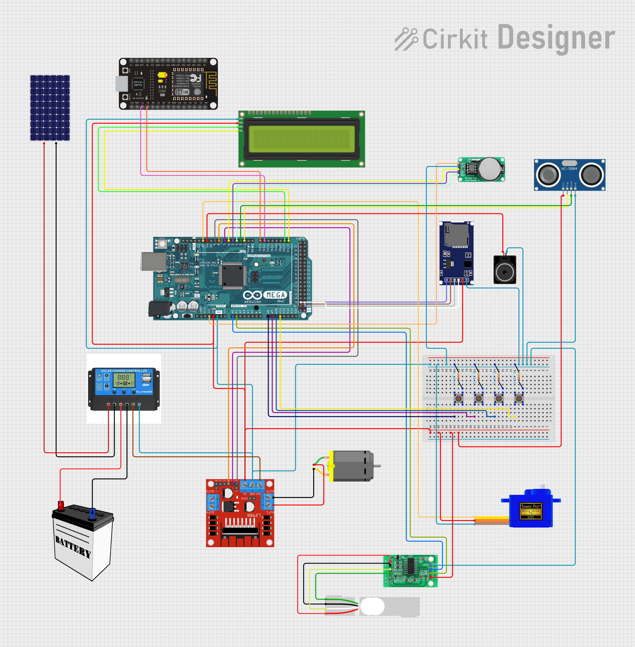
This circuit is designed to interface various components with an Arduino Mega 2560 microcontroller. It includes input devices (pushbuttons), output devices (DC motor, servomotor, loudspeaker, and LCD screen), sensors (ultrasonic sensor, load cell), a real-time clock (RTC), a motor driver, and communication modules (SD card module, ESP8266 WiFi module). The circuit is powered by a 12V battery regulated by a charge controller, which also interfaces with a solar panel for charging. The circuit's functionality is controlled by embedded code running on the Arduino Mega 2560.
Component List
Power Supply
- 12V Battery: Provides the main power source for the circuit.
- Solar Panel: Supplies power to charge the battery through the charge controller.
- Charge Controller: Manages the charging of the battery from the solar panel and provides power to the load.
Microcontroller
- Arduino Mega 2560: The central processing unit of the circuit, interfacing with all other components.
Sensors
- HC-SR04 Ultrasonic Sensor: Measures distance by emitting ultrasonic waves.
- Load Cell - Red/white/black/green: A weight sensor that measures force or load.
Actuators
- DC Motor: Converts electrical energy into mechanical motion.
- Servomotor SG90: A small rotary actuator that allows for precise control of angular position.
- Loudspeaker: Converts electrical signals into sound.
Display
- I2C LCD 16x2 Screen: A liquid crystal display that can show 16 characters per line on 2 lines.
Communication Modules
- SDmodule: An SD card module for data logging and storage.
- ESP8266 NodeMCU: A WiFi module for wireless communication.
Motor Driver
- L298N DC Motor Driver: Controls the direction and speed of the DC motor.
Timekeeping
- DS1302 RTC: A real-time clock for keeping track of the current time and date.
Interface
- Pushbuttons: Four pushbuttons used as input devices to interact with the microcontroller.
Miscellaneous
- Resistors: Four resistors, likely used for pull-up or pull-down configurations for the pushbuttons.
- HX711 - Bridge Sensor Interface: An ADC converter for the load cell sensor.
- Loudspeaker: An output device to produce audio signals.
Wiring Details
Power Supply
12V Battery:
VCCconnected to Charge ControllerBattery Positive.GNDconnected to Charge ControllerBattery Negative.
Solar Panel:
+connected to Charge ControllerSolar Positive.-connected to Charge ControllerSolar Negative.
Charge Controller:
Load Positiveconnected to L298N Motor Driver12V.Load Negativeconnected to common ground.
Microcontroller
- Arduino Mega 2560:
- Digital pins
D2toD12andD14toD53connected to various components for control signals. - Analog pins
A0toA11connected to sensors and pushbuttons. 5Vand3V3pins provide power to various components.GNDconnected to common ground.
- Digital pins
Sensors
HC-SR04 Ultrasonic Sensor:
VCCconnected to5Vfrom Arduino.TRIGconnected to Arduino pinD2.ECHOconnected to Arduino pinD3.GNDconnected to common ground.
Load Cell - Red/white/black/green:
E+,A-,E-,A+connected to HX711 Bridge Sensor Interface.
Actuators
DC Motor:
pin 1connected to L298N Motor DriverOUT1.pin 2connected to L298N Motor DriverOUT2.
Servomotor SG90:
SIGconnected to Arduino pinD12.VCCconnected to5Vfrom Arduino.GNDconnected to common ground.
Loudspeaker:
pin1connected to common ground.pin2connected to Arduino pinD11.
Display
- I2C LCD 16x2 Screen:
SCLconnected to Arduino pinD21/SCL.SDAconnected to Arduino pinD20/SDA.VCC (5V)connected to5Vfrom Arduino.GNDconnected to common ground.
Communication Modules
SDmodule:
CSconnected to Arduino pinD53.SCKconnected to Arduino pinD52.MOSIconnected to Arduino pinD51.MISOconnected to Arduino pinD50.VCCconnected to5Vfrom Arduino.GNDconnected to common ground.
ESP8266 NodeMCU:
TXconnected to Arduino pinD15/RX3.RXconnected to Arduino pinD14/TX3.- Other pins not specified in the net list.
Motor Driver
- L298N DC Motor Driver:
IN1connected to Arduino pinD7.IN2connected to Arduino pinD8.ENAconnected to Arduino pinD9.12Vconnected to Charge ControllerLoad Positive.GNDconnected to common ground.5Vconnected to5Vfrom Arduino.
Timekeeping
- DS1302 RTC:
VCCconnected to3V3from Arduino.GNDconnected to common ground.CLKconnected to Arduino pinD6.DATAconnected to Arduino pinD5.RSTconnected to Arduino pinD4.
Interface
- Pushbuttons:
- Each pushbutton has one pin connected to an Arduino analog pin (
A8toA11) and another pin connected to a resistor, which is then connected to common ground.
- Each pushbutton has one pin connected to an Arduino analog pin (
Miscellaneous
Resistors:
- Connected between pushbuttons and common ground.
HX711 - Bridge Sensor Interface:
E+,E-,A-,A+connected to Load Cell.GND - GROUNDconnected to common ground.DATA (OUT)connected to Arduino pinA0.SCK - CLOCK (IN)connected to Arduino pinA1.3.3/3.5V Supplyconnected to5Vfrom Arduino.
Documented Code
#include <L298N.h>

// Pin definition
const unsigned int IN1 = 7;
const unsigned int IN2 = 8;
const unsigned int EN = 9;

// Create one motor instance
L298N motor(EN, IN1, IN2);

void setup()
{
  // Used to display information
  Serial.begin(9600);

  // Wait for Serial Monitor to be opened
  while (!Serial)
  {
    //do nothing
  }

  // Set initial speed
  motor.setSpeed(70);
}

void loop()
{

  // Tell the motor to go forward (may depend by your wiring)
  motor.forward();

  // Alternative method:
  // motor.run(L298N::FORWARD);

  //print the motor status in the serial monitor
  printSomeInfo();

  delay(3000);

  // Stop
  motor.stop();

  // Alternative method:
  // motor.run(L298N::STOP);

  printSomeInfo();

  // Change speed
  motor.setSpeed(255);

  delay(3000);

  // Tell the motor to go back (may depend by your wiring)
  motor.backward();

  // Alternative method:
  // motor.run(L298N::BACKWARD);

  printSomeInfo();

  motor.setSpeed(120);

  delay(3000);

  // Stop
  motor.stop();

  printSomeInfo();

  delay(3000);
}

/*
Print some informations in Serial Monitor
*/
void printSomeInfo()
{
  Serial.print("Motor is moving = ");
  Serial.print(motor.isMoving());
  Serial.print(" at speed = ");
  Serial.println(motor.getSpeed());
}
This code snippet is designed to control a DC motor using the L298N motor driver. It sets up the motor with initial speed, runs the motor forward and backward, stops the motor, and prints the motor status to the serial monitor. The motor's speed is also adjusted within the loop.